
Simple Capacitor Tester

The LM3909 is an integrated circuit specifically designed for driving LEDs in a flashing pattern. It operates by charging and discharging a capacitor, which sets the timing interval for the LED's on and off states. The frequency of the oscillation is primarily influenced by the capacitance value and the resistor connected to the timing circuit.
In practical applications, a capacitor larger than 500µF can be employed to achieve slower flashing rates, allowing for easier visual frequency counting. When the circuit is powered, the capacitor begins to charge through a resistor until it reaches a threshold voltage, at which point the LM3909 activates the LED, illuminating it. The LED remains lit for a predetermined duration before the capacitor discharges, causing the LED to turn off. This cycle repeats, creating a flashing effect.
To set up the LM3909 LED flasher circuit, the following components are typically required: the LM3909 IC, a resistor (R) to limit the charging current, and a capacitor (C) to determine the timing. The values of R and C can be adjusted to achieve the desired flashing frequency. Additionally, a power supply is necessary to provide the required voltage to the circuit, usually in the range of 3V to 15V.
The circuit can also be enhanced by incorporating additional features, such as a switch to enable or disable the flashing, or multiple LEDs to create a more complex visual effect. The versatility of the LM3909 allows it to be used in various applications, including decorative lighting, indicators, and educational tools for demonstrating frequency counting. An LM3909 LED flasher is used as an oscillator, and the capacitor connected to the terminals determines frequency. The LED can be used to count frequency visually using a stopwatch for large capacitors (C > 500uf).
Related Circuits

Gates G1 and G2, along with resistors R1 and R2, create a straightforward voltage monitor with a trip point set at 1 volt. Gate G3 functions as an inverter. The display section of the tester features a common anode...
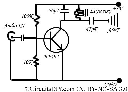
This is a simple and inexpensive FM transmitter. The circuit operates at a low voltage using a CR2025 3V battery with low current consumption. The total size of this FM transmitter, including the battery but excluding the antenna, is...

The circuit within the dotted line for a mini emergency light can be integrated into any battery eliminator, provided the eliminator's voltage exceeds that of the battery. For increased load capacity (i.e., for greater illumination through a larger lamp),...

This circuit is designed for monitoring an amateur band or a specific segment of the radio spectrum. It utilizes an NE602 mixer-oscillator chip to generate a 455-kHz intermediate frequency (IF) signal. This signal is amplified by U2 and subsequently...

The project "DIY: Build a Sound Activated Switch" presented here is straightforward to construct and can be very useful in protecting a specific area from potential theft or intrusion. Learn how to build a simple sound-activated alarm here on...
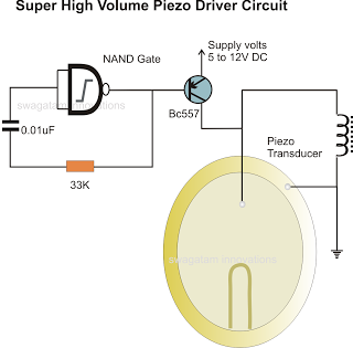
In the previous post, a piezo transducer element was discussed, along with its application in electronic circuits. This article will explore how a piezo transducer can be driven or operated using a simple circuit. The amplification method differs from...