
555 capacitance frequency transistor-line detector

The described frequency detection circuit is an essential tool for measuring capacitance and frequency through a systematic approach involving a relaxation oscillator and a transistor testing mechanism. The use of a 555 timer provides a stable timing reference, while the adjustable resistors R8 to R12 allow for fine-tuning of the pulse width in relation to the measured capacitance Cx. The incorporation of the K1 switch facilitates user interaction, enabling the selection of measurement modes—either capacitance detection or frequency measurement.
In the capacitance measurement mode, the circuit's design ensures that as the capacitance increases, the output pulse width also extends, which can be directly correlated to the average output current. This characteristic is crucial for applications requiring precise capacitance values. The relaxation oscillator formed by BG1, R1, and C3 generates a consistent pulse train that serves as the triggering mechanism for the IC, ensuring reliable operation.
When measuring frequency, the circuit maintains a fixed output width, allowing for consistent readings across varying input signal frequencies. This feature is particularly valuable in applications where frequency stability is critical. The online transistor testing functionality provides a straightforward means of assessing transistor health, with LED indicators offering instant feedback on operational status.
Overall, this frequency detecting circuit exemplifies a well-integrated design that combines capacitance measurement, frequency analysis, and transistor testing into a single, versatile platform, making it an invaluable asset in electronic testing and diagnostics. The design principles employed ensure robustness and reliability, catering to a range of electronic applications. As shown for the capacitor, the frequency detecting circuit transistor line. Can be converted by adjusting the preset switch K1 when this detector capacitance, frequency, trans istor testing. The K1 placed II detectable capacitance. 555 and R8 ~ R12 and measured capacitance Cx composition single stabilizing circuit, Cx capacity is increased, the pulse width, ie td 1.1 (R8 ~ R12) Cx longer, the greater the current average, indicating that the corresponding header greater. Circuit BG1 single junction transistor with R1, C3 composition relaxation oscillator, the oscillation output pulse signal as a trigger pulse of the IC.
The K1 placed III frequency measurements can be carried out. At this one-shot circuit IC output td signal 1.1 (R8 ~ R12) CB fixed value width. The higher the frequency of the input signal. Frequency IC is triggered, the more the greater the average current, the greater the corresponding table header indicates. The K1 place I can be online test transistor. The principle is similar to the detection capacitor. Circuit transistor BG1 complete positive and negative power conversion. With IC output high and low alternating changes, if the light-emitting diodes LED1, LED2 turn light, then the transistor is good, otherwise the transistor is bad.
Related Circuits
Pulses are received by the timer from the distributor points. When the timer output is high, Meter M receives a calibrated current through R6. The meter does not... The circuit described involves a timer that receives pulse signals from distributor...
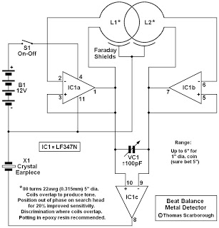
This is a metal detector circuit where the frequencies of two oscillators are mixed in a manner similar to a Beat Frequency Oscillator (BFO) to produce an audible heterodyne signal. At first glance, this design may appear to be...
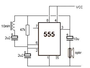
A simple metal detector circuit can be implemented using a 555 timer chip. The schematic diagram illustrates that this project requires only a few external electronic components. The metal detector circuit utilizing a 555 timer operates in astable mode, generating...
This document presents an intriguing collection of frequency dividers with division factors ranging from 2 to 10. All options are based on the 7490, which is a decade and binary counter. The frequency dividers utilizing the 7490 integrated circuit (IC)...

Portable devices such as video cameras, halogen floodlights, electrical irons, hand drills, grinders, and cutters are powered by connecting long 2- or 3-core cables to a mains plug. Prolonged use can subject the power cord wires to mechanical strain...
This is a short-range light barrier designed for use as an intruder alarm in doorposts and similar applications. The 555 timer in the transmitter oscillates at approximately 4.5 kHz. The short-range light barrier operates by utilizing a transmitter and a...