
Car Tachometer with 555 IC

The circuit described involves a timer that receives pulse signals from distributor points, which are likely part of an ignition system in an automotive or similar application. The timer is responsible for processing these pulses and determining when to activate its output signal.
When the timer output is in a high state, it allows current to flow through a resistor, denoted as R6. This resistor is crucial as it helps to limit the current to a safe level for the meter, referred to as Meter M. The meter is designed to display a calibrated reading, which could represent various parameters such as voltage, current, or another measurement relevant to the system's operation.
The interaction between the timer and Meter M is essential for monitoring the system's performance. The calibrated current flowing through R6 ensures that the meter operates within its specified range, providing accurate readings. This functionality is critical in applications where precise measurements are necessary for system diagnostics or performance tuning.
Further analysis of the circuit may involve examining the specifications of the timer, the characteristics of the pulses being received, and the calibration details of Meter M. Additionally, understanding the role of R6, including its resistance value and power rating, will contribute to the overall reliability and accuracy of the circuit. Properly designed, this system can enhance the monitoring capabilities of the application it serves, ensuring optimal performance and safety.Pulses are received by the timer from the distributor points. When the timer output is high, Meter M receives a calibrated current through R6. The meter don`t.. 🔗 External reference
Related Circuits
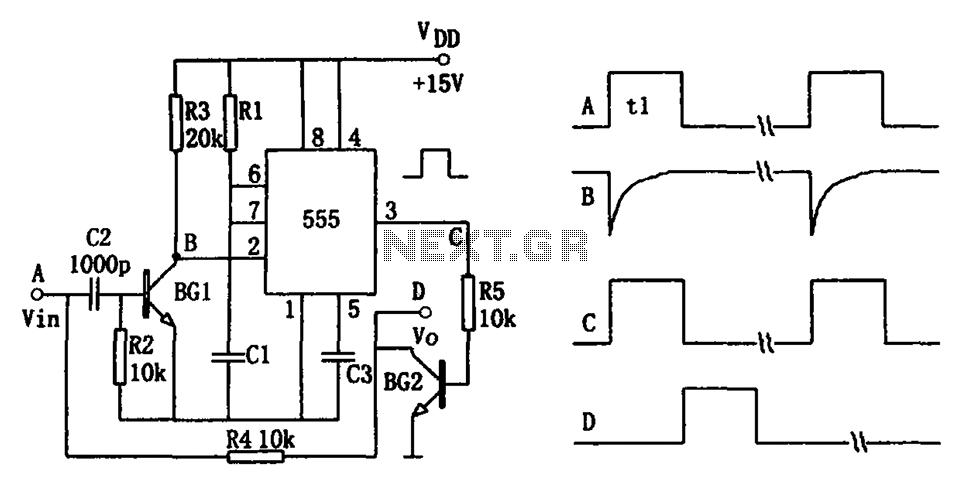
The pulse-width detection circuit is illustrated in the figure and consists of a differential circuit (R2, C2), an amplifier (BG1), a single stabilizing circuit (555, R1, C1), and various other components. The pulse signal Vin (depicted as waveform A)...
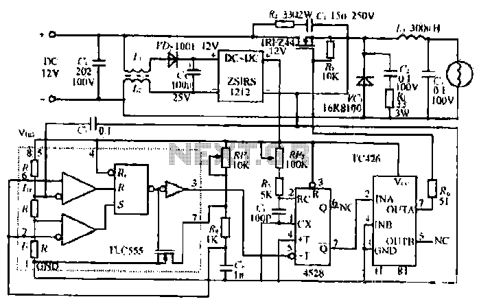
The circuit utilizes a Bute CD12V Lee power MOSFET transistor (BU1RF744) that operates in a switching mode, turning on and off repeatedly. The output voltage is influenced by the characteristics of the MOSFET, which is designed for efficient performance....
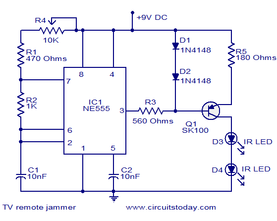
Here is the circuit diagram of simple but highly effective TV remote jammer circuit. Most of the TV remotes have 38KHz operating frequency. A flood of IR beams in the same frequency can easily confuse the TV receiver and...
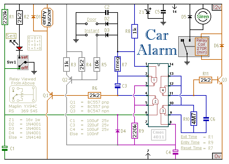
This circuit is designed to secure a vehicle at a low cost if constructed independently, making it more affordable than purchasing a commercial car alarm system. The alarm is activated by opening switch Sw1, which can be any small...
The figure illustrates an NE555 frequency modulation (FM) circuit. In this circuit, pin 7 of the NE555 is connected to an FM modulation section that consists of resistor R5 and capacitor C2, although the frequency range is somewhat limited....
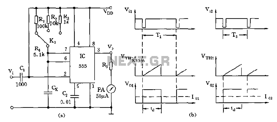
The circuit utilizes a 555 timer along with timing resistors R1 to R3 and a measured capacitance Cx to create a capacitance meter. The principle of capacitance measurement in a one-shot circuit is based on the relationship between the...