
555 Composition with Watchdog circuit

The power-delay control circuit operates by utilizing a resistor (R1) and a capacitor (C1) to establish a time constant that governs the delay period. When power is applied, the capacitor charges through the resistor, and the time taken for the capacitor to reach a certain voltage level dictates the delay time. This characteristic can be critical in applications where a delayed response is required, such as in power-up sequences or in systems that need to prevent immediate activation of components after power is applied.
The integration of a watchdog circuit enhances the functionality of the basic power-delay circuit. The watchdog circuit serves as a monitoring mechanism that ensures the system operates within predefined parameters. It can detect anomalies or malfunctions in the system's operation. If the system fails to reset or respond within a specified timeframe, the watchdog can trigger corrective actions, such as resetting the system or activating an alarm. This feature is particularly beneficial in applications where system reliability is paramount, such as in embedded systems, industrial controls, or safety-critical applications.
In a typical schematic, R1 and C1 would be connected in series, forming an RC timing circuit. The output of this timing circuit could be connected to a microcontroller or another control logic device, which would take action based on the voltage level across the capacitor. The watchdog circuit would typically include a timer and a reset mechanism that monitors the operation of the primary circuit. If the timer exceeds its limit without receiving a reset signal from the monitored system, it would initiate a predefined response to ensure safe operation.
Overall, this circuit design combines delay functionality with monitoring capabilities, making it suitable for a variety of applications that require both timing control and system oversight.This circuit was originally a type of power-delay control circuit, the delay time by the timing element Rl, C1 decision. But with the "watchdog" circuit, you can use it as a monitoring circuit for certain applications of the system.
Related Circuits
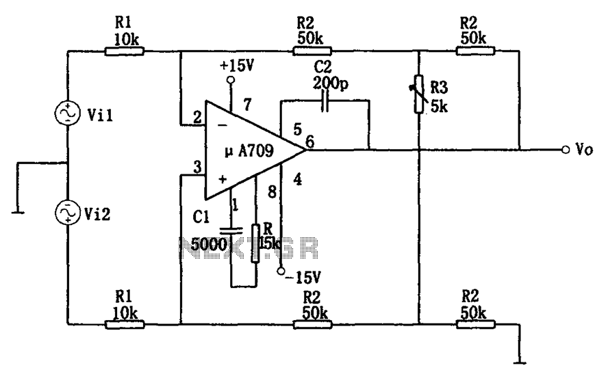
The configuration of the variable gain A709 differential amplifier circuit is illustrated. The primary advantage of this circuit is its ability to maintain a constant common-mode rejection ratio (CMRR) while allowing for continuous adjustments to the differential gain. The...
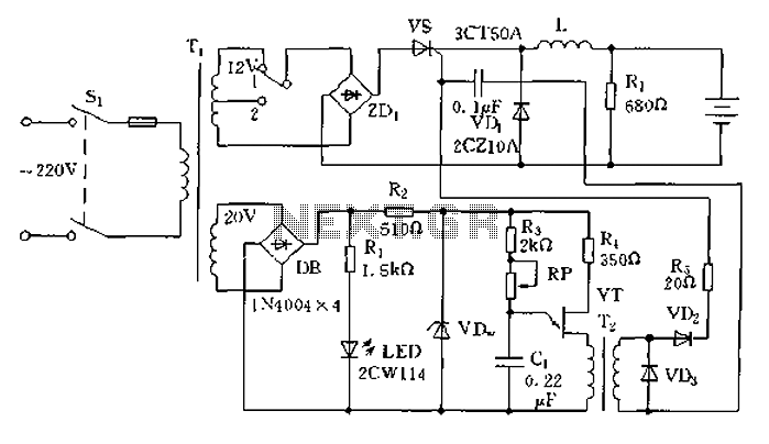
The circuit operates on the principle of a transformer, bridge rectifier, and conditioning for battery charging. The charging current can be adjusted to approximately 12V at 100A. For battery charging, a charging rate of 10 hours requires a charging...
The Zero Volt Diode (ZVD) is a circuit useful in various applications, including solar chargers of all types. It is a novel circuit where a power MOSFET functions as a very low voltage drop diode, switching states at 0V...
The following circuit illustrates a 2500W Phase Control Circuit Schematic. Features include a ground-tied trigger output that is disabled, and a low voltage input. The 2500W Phase Control Circuit is designed to regulate the power delivered to a load by...
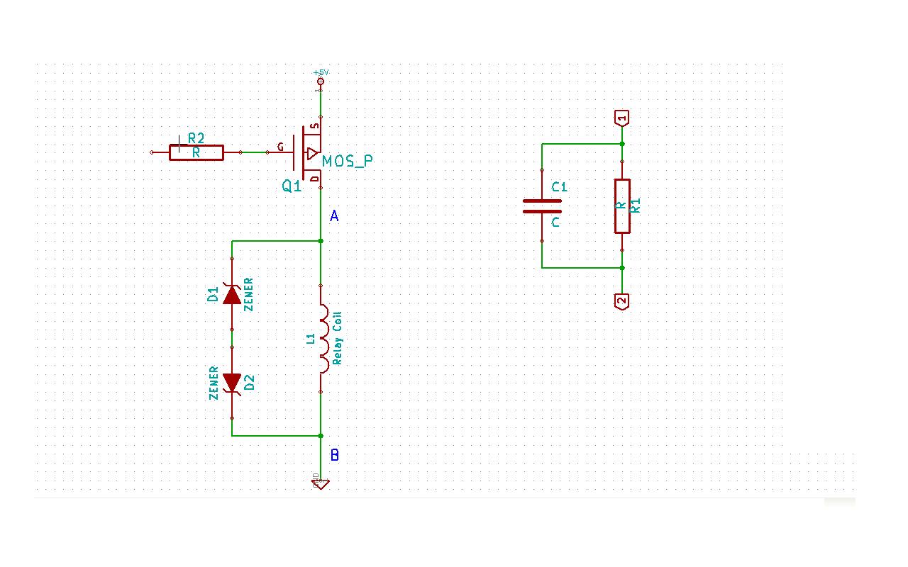
Although this may be a basic question, there is still some struggle with it. In this schematic, two zener diodes D1 and D2 are connected back-to-back across relay coil L1. The breakdown voltage (BVds) is -30V for Q1. The...

The schematic for this tutorial is illustrated below and includes all necessary components for the tutorial to function. The PIC programming circuitry is not included, as it is assumed that the PIC is either programmed externally or that the...