
555 Electronic Metronome Circuit

The metronome circuit is a timing device that generates a regular pulse signal, typically used in music practice to maintain a steady tempo. The 555 timer IC, a versatile and widely used component, can be configured in astable mode to produce this pulsing output. The configuration provided by ON Semiconductor and National Semiconductor highlights the importance of proper component placement and values in achieving the desired frequency output.
In the proposed circuit, the connection of pins 2, 6, and 7 is crucial. By separating these pins and incorporating resistors Ra and Rb, the timing characteristics of the circuit can be fine-tuned. Resistor Ra connects the supply voltage to pin 7, ensuring the timing capacitor can charge through this resistor. Resistor Rb, positioned between pin 7 and pin 6, influences the discharge path of the timing capacitor, allowing for control over the frequency of oscillation.
The capacitor between pin 6 and ground plays a significant role in defining the timing intervals. The output frequency formula, f = 1.44 / C[Ra + 2Rb], indicates that adjusting the values of Ra and Rb, as well as the capacitor C, will directly affect the frequency of the metronome. It is essential to use precise component values to achieve the desired frequency range.
The recommendation for a 0.01 µF capacitor between pin 5 and ground serves to stabilize the voltage at pin 5, which is the control voltage pin of the 555 timer. This capacitor helps filter any noise that may affect the timer's operation, ensuring a more stable output frequency.
Regarding the audio output, the use of an LM386 audio amplifier is appropriate for boosting the sound level produced by the metronome circuit. However, the choice of loudspeaker must align with the amplifier's specifications to prevent distortion or damage. It is advisable to review the maximum power rating of the loudspeaker to ensure compatibility with the LM386, which can deliver up to 1 watt of output power. If the sound level remains low, consider adjusting the gain settings on the LM386 or exploring alternative loudspeakers with higher sensitivity.I have assembled the metronome circuit several times and it did not work. Two 555 manufacturers websites (ON Semiconductor and National Semiconductor) propose circuits that differ from yours in that pins 2/6/7 are not joined together but there is a resistor Ra between +Vcc and pin 7, a resistor Rb between pin 7 and pin 6 (= pin 2 ) and the capacitor is between pin 6 and ground. The output frequency is f=1. 44/C[Ra+2Rb]. Both manufacturers ask for a 0. 01 f capacitor between pin 5 and ground. It would have been helpful to specify the maximum power rating of the loudspeaker. The sound level I am getting is quite low and am trying to use an LM386 audio amplifier. Any suggestion Mula ±umiri 🔗 External reference
Related Circuits
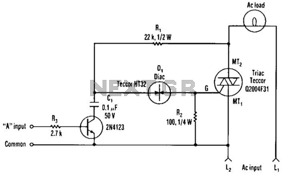
The single transistor connected between the capacitor and the common side of the AC line allows a logic-level signal to control this TRIAC power circuit. Resistor R2 prevents false triggering of the TRIAC by the trickle current through the...
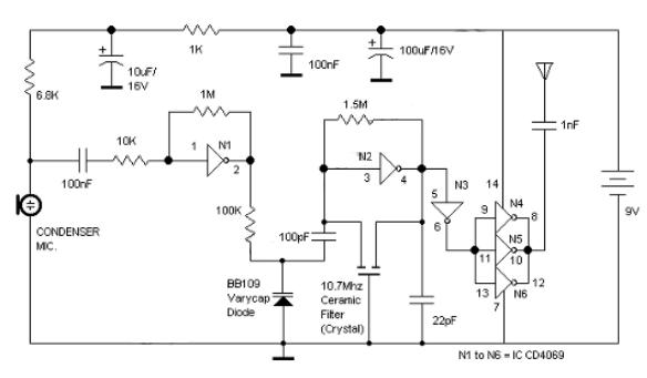
Logic Gates FM Transmitter Circuit Electronic Circuit Schematic Wiring Diagram. The FM transmitter circuit utilizing logic gates is a fundamental electronic design that operates by modulating a carrier frequency with an audio signal. This circuit typically consists of various logic...
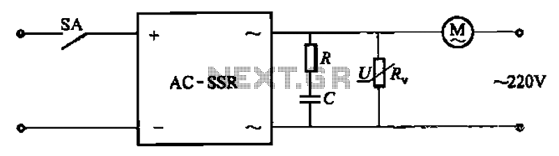
The circuit illustrated in Figure 3-13 is an RC surge absorption circuit that includes a resistor (R) and zinc oxide varistors (such as MY31, MYH12, MYH20 types, etc.), which serve as an overvoltage protection device. The resistance R is...
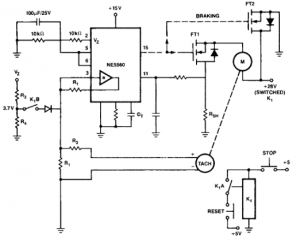
This circuit is useful for creating a constant speed motor control, ensuring that the motor speed remains constant despite variations in load and electrical voltage. The circuit for a constant speed motor control typically employs feedback mechanisms to maintain a...
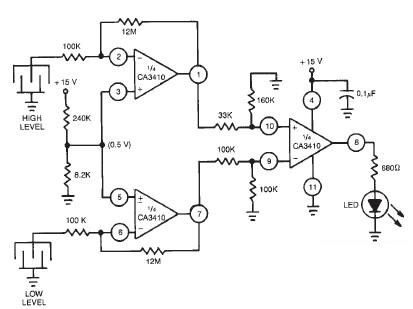
This liquid level sensor electronic circuit diagram utilizes a common CA3410 operational amplifier integrated circuit (IC). The sensor employs two plate sensors (or probes), one designated for detecting high liquid levels and the other for low liquid levels. If...
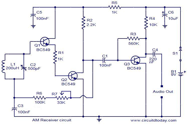
Circuit diagram of a modulator circuit in a transmitter and receiver of amplitude modulation. The modulator circuit in an amplitude modulation (AM) transmitter and receiver plays a crucial role in the process of encoding information onto a carrier wave. In...