
Sensitive Triac Controller Circuit

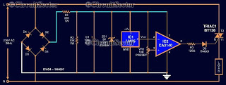
The described circuit utilizes a single transistor as a control element, interfacing a low-voltage logic signal with a TRIAC, which is capable of handling higher power applications. The transistor is positioned between a capacitor and the common side of the AC line, effectively allowing the logic-level signal to initiate the TRIAC's conduction state. This configuration is particularly useful in applications where microcontrollers or other digital logic devices need to control AC loads.
The capacitor serves as a timing element that, when charged, can influence the base of the transistor. When the logic signal is applied, it turns the transistor on, allowing current to flow and subsequently triggering the TRIAC to conduct. The TRIAC remains in the 'on' state until the current through it drops below a certain threshold, thereby allowing it to control AC power to the load.
Resistor R2 plays a crucial role in ensuring the stability of the circuit by preventing false triggering of the TRIAC. It limits the trickle current that can flow through the DIAC, which is a device that typically requires a certain threshold voltage to turn on. Without R2, even small fluctuations in the circuit could inadvertently trigger the TRIAC, leading to unwanted operation of the connected load. By carefully selecting the value of R2, the circuit designer can ensure that only intentional signals from the logic device will activate the TRIAC, thus enhancing the reliability and performance of the overall system.
This configuration is widely used in applications such as light dimmers, motor speed controls, and other AC power control scenarios, where precise control over the load is necessary while maintaining the integrity of the low-voltage control signal. The single transistor connected between the capacitor and the common side of the ac line allows a logic-level signal to control this triac power circuit. Resistor R2 prevents false triggering of the triac by the trickle current through the diac.
Related Circuits
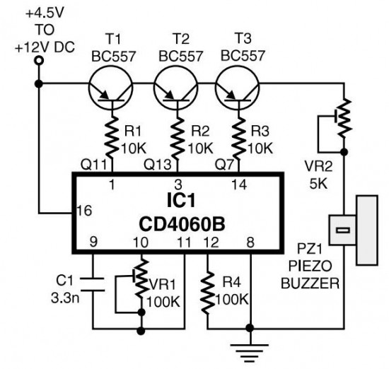
The circuit generates pulses of 1.25 Hz from pin 1 and 20 Hz from pin 14. The three output pins of IC1 are connected to the base terminals of transistors T1, T2, and T3 through resistors R1, R2, and...
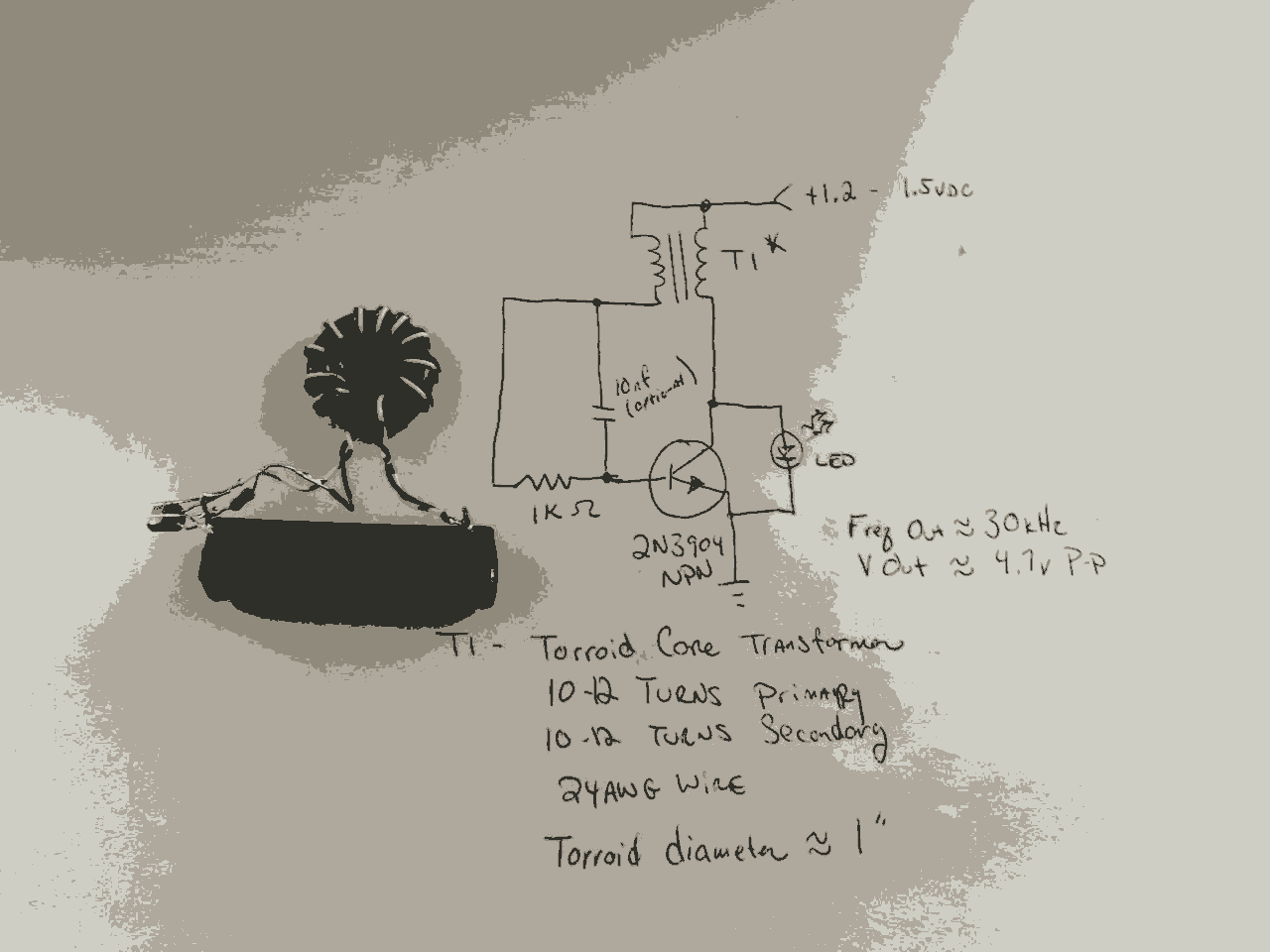
In the previous post, the primary principles of the switching power supply were discussed. Essentially, an oscillator drives a transformer with a ferrite core at a relatively high frequency, thereby minimizing the size, weight, and cost of power supplies....
Computers often experience overheating due to prolonged use or high ambient temperatures, making temperature controllers essential. Accurate temperature measurement is necessary to ensure that the computer operates within a safe temperature range. A circuit diagram for a simple temperature...
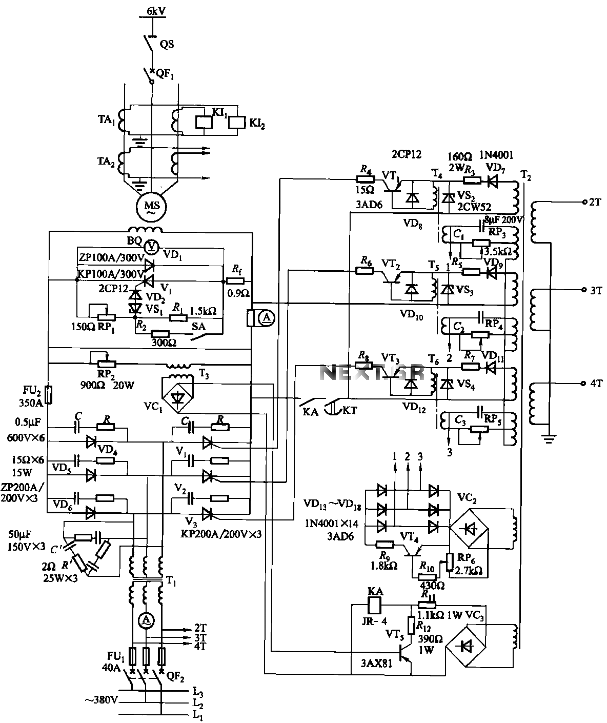
The excitation device for a light-duty synchronous motor rated at 625 kW has been initiated. The triggering circuit of the device consists of three identical RC phase-shift flip-flops. Adjustment potentiometers RP3 to RPs are used to set the RC...
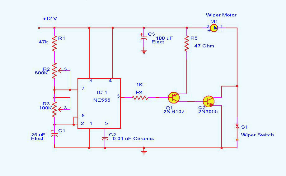
DC motor control circuit using NE555. The 555 timer circuit has numerous applications. For those unfamiliar with its functionalities, an authoritative book can provide valuable insights. CircuitsToday offers an online store featuring reviews of three highly recommended books that...
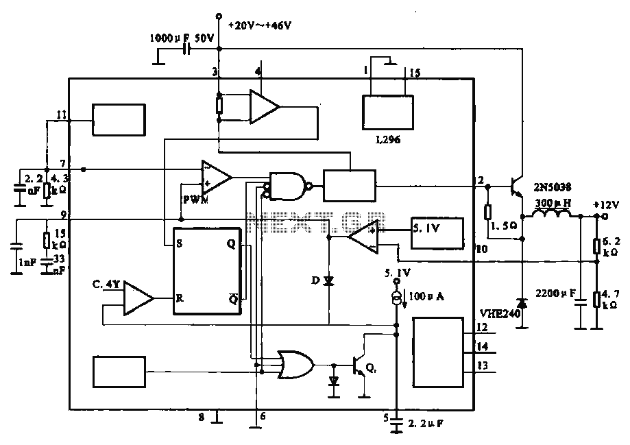
The circuit outputs 12V at 10A and utilizes a high-current switching power supply design based on the L296 component. This configuration allows for an output current of up to 10A, and the entire circuit is compact with minimal component...