
555 high performance photovoltaic street a control circuit diagram

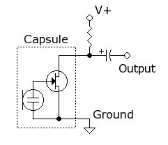
The optical control circuitry functions as an intelligent lighting management system designed for street applications, utilizing a combination of analog and digital components to ensure reliable operation. The core of the circuit is the Light Dependent Resistor (LDR), which serves as an input sensor that detects ambient light levels. The LDR's resistance varies inversely with the light intensity; in bright conditions, its resistance decreases, allowing more current to flow through the circuit, while in darkness, its resistance increases, reducing current flow.
The comparator circuit, implemented with a 555 timer IC, is configured in a bistable mode to switch states based on the voltage levels from the LDR. When the LDR detects sufficient ambient light, the output from the 555 timer remains high, which prevents the relay from engaging. The relay's role is to control the main power supply to the street lights, ensuring they are off during the day.
As night falls and the LDR's resistance increases due to the lack of light, the voltage at the comparator's input drops, triggering a transition in the 555 timer's output to low. This change activates the relay, turning on the street lights (LED1).
Additionally, the circuit includes a stabilizing mechanism through IC2, which works in conjunction with components BG1 and BG2 to form an action locking loop. This loop is critical in preventing the relay from chattering or toggling due to minor fluctuations in light levels that could occur around dusk and dawn. The timing capacitor (C6) and resistor (R7) determine the delay period for the relay activation, set to approximately 10 minutes, allowing for a stable transition that avoids rapid on-off cycling of the lights.
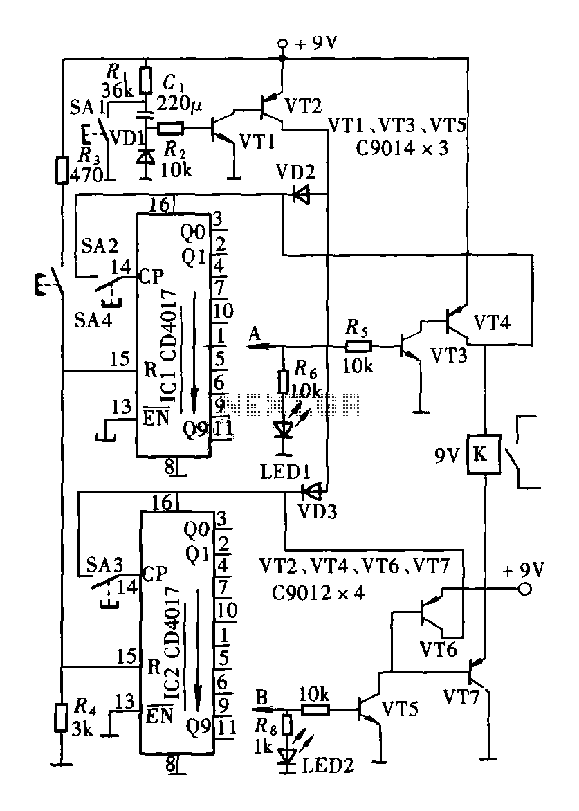
The implementation of this circuit provides a robust solution for street lighting control, enhancing energy efficiency and ensuring that lights are only operational when necessary. The design minimizes maintenance issues associated with relay chatter and provides a reliable operation across varying environmental conditions. As shown in FIG optical control circuitry for high-performance street. The circuit consists of a photoelectric conversion element LDR, comparator circuit IC1 (555), single stab ilizing circuit IC2 and other components. Wherein IC2 and BG1, BG2 constitute action locking loop, LDR components using photoresistor.When the LDR exposed to light, it was a low-resistance, low input pin 555 due occurs set, feet high output, and therefore the relay J does not act, the light emitting diode LED1 does not emit light. Night, LDR light and was not due to high resistance, due 555 feet high and the reset input occurs, pin output low, so that the relay J pull, LED LED1 light.
This time it triggers IC2 work, so that the output timing of the td 1.1R7C6 (about 10 minutes) signal corresponding light emitting diode LED2 light. Thus within l0 minutes, the relay can be solved in critical action point unstable. Circuit action locking circuit can also overcome the disadvantages of the relay at the critical point due to the action of light instability and frequent changes in operation.
Therefore, this circuit to achieve high performance photoelectric controls on lights.
Related Circuits

Useful for A/B control, the IR receiver shown controls a relay from an infrared beam that has a pulsed tone-modulated signal. Q1 is the photo receptor feeding op amp IC1, tone decoder IC2, and flip-flop IC3. IC5 turns off...
A simple circuit is desired that utilizes a microphone to capture voice and transmit the audio signal to a speaker. The objective is to understand the connections required for integrating a microphone into the circuit. To create a basic microphone-to-speaker...

A headphone type detection circuit is illustrated in the attached figure. The 2.2k RMIC-BIAS resistor connected to the audio controller provides a low-noise reference voltage (VMIC-REF). When the audio jack is inserted, the VMIC-REF voltage through RMIC-BIAS is applied...
This document presents plans for a simple ground plane antenna that is effective in the FM band (88-108 MHz). It is constructed from a small plastic disk. The 6 x 6 loop antenna, designed by Graham Maynard, is highlighted...
The circuit consists of a two and four decimal counter CD4017 used in conjunction with a password switch. It is composed of the output terminals from the key switch logic combination of components, which provide another feature of the...
This circuit is designed to serve as a programmable LED display for various applications. It features an 8 x 32 LED dot matrix interfaced with a Xino (or Arduino). In addition to the display, the circuit includes two buttons...