
simple microphone circuit

To create a basic microphone-to-speaker circuit, several key components are necessary, including a microphone, an operational amplifier (op-amp) for signal amplification, a speaker, and a power supply. The following outlines the steps to assemble this circuit:
1. **Microphone Selection**: Choose an electret condenser microphone, which is commonly used for audio applications due to its sensitivity and ease of use. This type of microphone typically requires a bias voltage, which can be supplied through a resistor connected to the power supply.
2. **Biasing the Microphone**: Connect the positive terminal of the microphone to a suitable voltage source (e.g., +5V) through a resistor (typically 1kΩ). The negative terminal of the microphone should be connected to the ground. The output signal of the microphone will be taken from the junction between the microphone and the resistor.
3. **Signal Amplification**: The output from the microphone is a weak audio signal that needs amplification. An op-amp can be configured in a non-inverting amplifier configuration. Connect the output of the microphone to the non-inverting input of the op-amp. The op-amp should be powered by the same voltage supply used for the microphone. Feedback resistors (such as 10kΩ and 1kΩ) can be used to set the gain of the amplifier.
4. **Connecting the Speaker**: The amplified output from the op-amp can be fed directly to a small speaker. If the speaker requires a higher power level, a transistor can be used to drive the speaker. Connect the output of the op-amp to the base of the transistor through a resistor (e.g., 1kΩ). The collector of the transistor should be connected to the positive terminal of the speaker, while the emitter is grounded.
5. **Power Supply Considerations**: Ensure that all components are powered appropriately, and verify that the total current draw does not exceed the ratings of the power supply. Use decoupling capacitors (e.g., 10µF) across the power supply lines to reduce noise.
6. **Testing the Circuit**: Once assembled, test the circuit by speaking into the microphone and observing the sound output from the speaker. Adjust the gain of the op-amp as necessary to achieve the desired volume level.
This configuration provides a straightforward method for capturing audio input and converting it into audible output through a speaker, ideal for basic audio applications.I want to make a simple circuit with a microphone that just takes your voice and sends it to a speaker. I just want to understand how to hook up a mic.. 🔗 External reference
Related Circuits
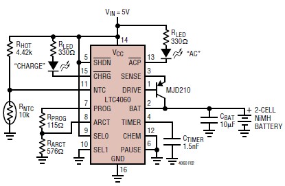
The LTC4060 integrated circuit can be utilized to create a straightforward smart NiMH battery charger electronic project. This charger circuit functions as a complete fast charging system for NiMH or NiCd batteries. It requires only a few external components...
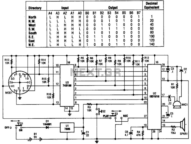
A talking compass consists of a Hall-effect direction sensor (MODI) and an ISD1016 analog audio storage device. It can store eight two-second announcements for each of the eight primary compass directions. The Talking Compass includes a digital compass (MODI),...
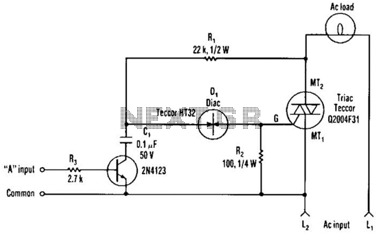
The single transistor connected between the capacitor and the common side of the AC line allows a logic-level signal to control this TRIAC power circuit. Resistor R2 prevents false triggering of the TRIAC by the trickle current through the...
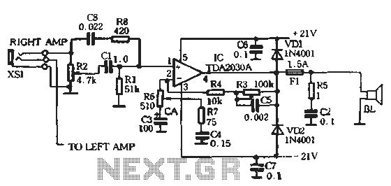
The circuit comprises two main components: the Lisheng power amplifier and the rectifier filter section. The stereo audio power amplifier circuit diagram, depicted in Figure 5-85, illustrates only one channel, with the other channel being identical. The audio signal...
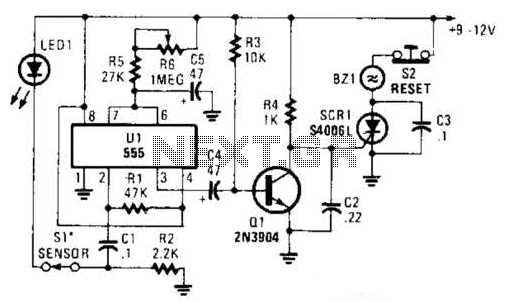
The alarm circuit utilizes a single 555 oscillator/timer (U1) that functions in both the alarm-trigger circuit and the entry-delay circuit. In this configuration, the trigger input of U1 at pin 2 is maintained in a high state through resistor...
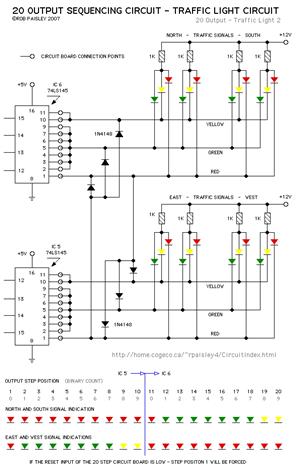
The current application involves the use of the VHDL hardware description language for designing a traffic light system controller circuit. This design is implemented within the Altera MAX PLUS EDA software environment, which facilitates compilation, simulation, and programming for...