
555 ics hysteresis for dark activated

This circuit operates on the principle of light intensity sensing using an LDR in conjunction with a 555 timer configured in a comparator mode. The 555 timer's thresholds are critical for establishing the points at which the relay will activate and deactivate. When the ambient light level decreases, the LDR's resistance increases, resulting in a higher voltage at the input pin of the 555 timer. Once this voltage exceeds 2/3 of the supply voltage, the output of the 555 timer switches from a low to a high state, activating the relay.
The hysteresis feature is vital for preventing rapid on-off cycling of the relay, which can occur if the light levels fluctuate around the threshold. With hysteresis, the activation point (2/3 of the supply voltage) is distinct from the deactivation point (1/3 of the supply voltage). This ensures that the relay remains engaged until a significant increase in light intensity occurs, thereby providing a stable operation in varying light conditions.
The choice of LDR or CDS cell is essential, as these components exhibit varying resistance based on the light levels they are exposed to. The selected resistance range of 2 to 8 kΩ is optimal for achieving the desired sensitivity and response time. Additionally, the circuit can be powered by a supply voltage of 12V, which is common in many applications, ensuring compatibility with standard relay modules.
In summary, this circuit effectively utilizes the properties of a 555 timer IC alongside an LDR to create a reliable light-activated relay system with hysteresis, suitable for applications requiring automatic control based on ambient light conditions.This is a circuit that can be used for dark activated means the relay will be activated when thelight intensity fall below a certain threshold. Without hysteresis, the relay will be activated and deactivated if the sensed brightness fall under or rise above a single point of darkness level.
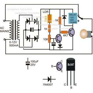
With hysteresis, the darkness level for activating and de activating the relay will be different, and this solve the relay oscillation problem when the light intensity is swinging up and down around a single point of no hysteresis activation level. Here`s the figure of the circuit; We can employ the hysteresis of a 555 IC to improve the sensingof a drop in light, since the internal 555 circuit has 1/3 and 2/3supply voltage thresholds.
We have to use a LDR or CDS cell with out 2 to 8 k resistance at desired light level. At the dark, the resistance of the LDR will rise and activate the relay if the voltage at pin 2 reach 2/3 of supply voltage (8V). After the relay is activated, more light is needed to make the LDR decrease its resistance until the voltage at pin 2 falls below 1/3supply voltage (4V).
🔗 External reference
Related Circuits
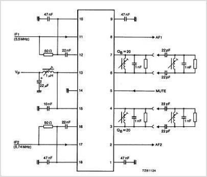
The TDA3567 is a monolithic integrated decoder designed for the NTSC color television standards. It incorporates all the necessary functions for the demodulation of NTSC signals. Additionally, it features a luminance amplifier and an RGB matrix amplifier. These amplifiers...
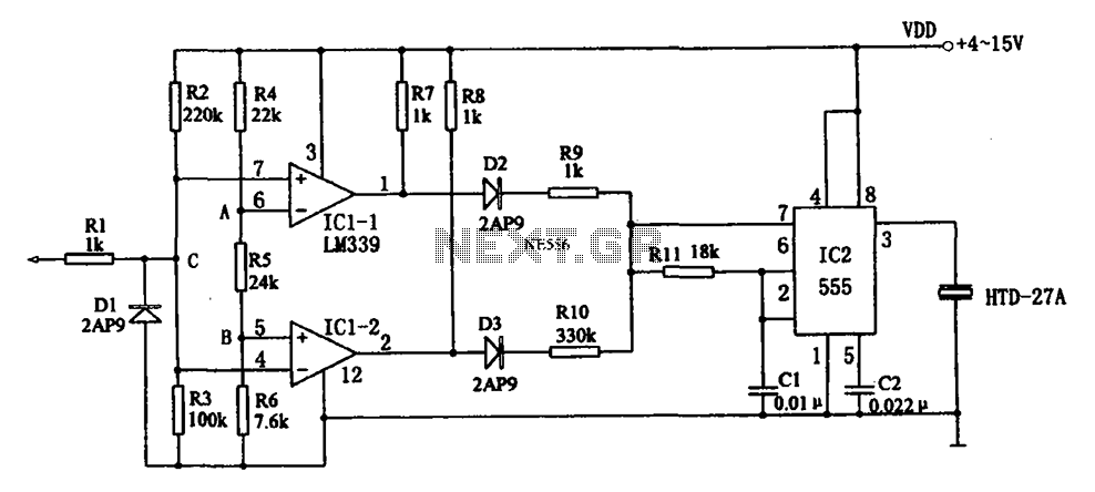
The acoustic logic level probe circuit consists of a voltage comparator, multivibrator, piezoelectric ceramics (HTD), and other components. The configuration of the audio circuit determines the frequency of the sound level to assess the logic levels of TTL or...
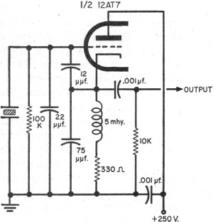
The fundamentals of crystals have not changed since this article appeared in a 1960 edition of Popular Electronics. The methods for growing, cutting, and packaging crystals have evolved significantly. Understanding their operation at the atomic level has also advanced...
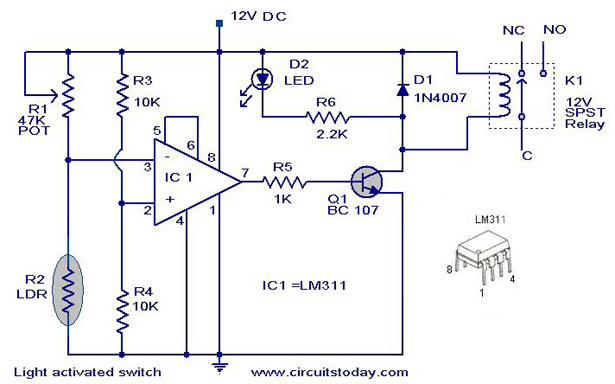
A simple light-activated switch circuit with a diagram and schematic using IC LM311 wired as a voltage comparator and an LDR that acts as a light sensor. The described circuit utilizes the LM311 integrated circuit, which functions as a voltage...
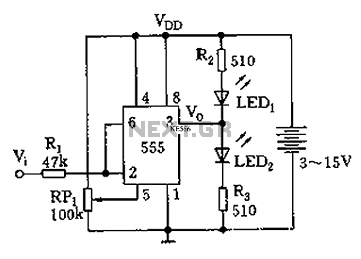
Figure 555 illustrates a simple logic circuit test lead. The test pen utilizes the 555 timer IC as its core component, incorporating a Schmitt trigger to assess the logic state of digital circuits. The circuit has two outputs: when...
This circuit diagram illustrates a light-activated switch utilizing the National Semiconductor comparator IC LM311 and a light-dependent resistor (LDR). The configuration is based on a voltage comparator circuit centered around IC1. The non-inverting input of IC1 receives a reference...