
555 logic test circuit diagram pen

The circuit primarily utilizes a 555 timer IC configured in a monostable or astable mode, depending on the desired application. The Schmitt trigger feature provides hysteresis, which is critical for distinguishing between high and low logic levels in noisy environments. The input signal is connected to pin 2 (trigger) of the 555 timer, while pin 6 (threshold) is used to determine the switching points for the LEDs.
LED1 and LED2 serve as visual indicators of the logic state. The adjustment potentiometer (RP1) allows for fine-tuning the reference voltage at pin 5, which is essential for accurate testing of digital circuits. The resistor values and capacitor connected to the 555 timer are selected to ensure that the timing characteristics suit the application, providing stable operation across a range of input conditions.
In the context of testing a -24V PMOS circuit, the circuit is designed to withstand higher input voltages, ensuring that the 555 timer operates correctly without damage. The output states of the LEDs provide immediate feedback on the logic level, which is crucial for troubleshooting and verifying the functionality of digital components. This circuit can be an invaluable tool for engineers and technicians working with digital electronics, allowing for quick assessments of circuit performance and integrity. As shown in Figure 555 is a simple logic circuit test leads. Test pen 555 as the core, it will take a Schmitt trigger, the logic state of the test for digital circuit. 2,6 555 feet and then, when the input signal level is 0, 555 set, LED2 light; when the input is 1, LED1 lights. For example, when Vdd 4.5V, the measurement TTL circuit, adjust RP1, so 5 feet potential 2.4V, the Schmitt trigger R end (6 feet) trigger level 2.4V, S end (2 feet ) level is 1.2V.
When the input level is higher than 2.4V, LED1 lights; below 1.2V, LED2 light. This circuit is used to test the operating voltage of -24V PMOS circuit.
Related Circuits
This complete aerial quality, low noise address audio amplifier is based on the Hybrid Integrated Circuit STK4050 manufactured by Sanyo. The circuit incorporates all necessary components and has a maximum output power of 200W. It features an onboard power...

The circuit utilizes two main components: an integrated electronic tuner with AV output, commonly referred to as the tuner, which can receive CATV full channel TV signals and output a video signal (Vttko) along with an audio signal (Audio)....
Solar battery charger schematic and description. This solar battery charger circuit is capable of charging a 12V lead-acid battery or sealed lead-acid (SLA) battery. The solar battery charger circuit is designed to convert solar energy into electrical energy for charging...

A current source (MPF102) in the source lead of the bipolar transistor 2N3906 allows for precise control of drain current. The circuit incorporates an MPF102 JFET configured as a current source, which is connected to the source terminal of a...
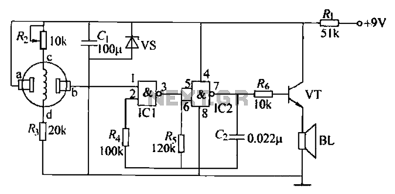
The combustible gas alarm circuit is depicted. The circuit comprises a gas sensor, a multivibrator, and audio output components. The multivibrator is implemented using two NAND gates within an integrated circuit (IC2) and includes external resistive and capacitive components....
This is another kit in our self-sufficiency range. We also have a 12v fluoro inverter kit for those who need to operate 20watt to 40watt fluorescent lamps from a 12v supply. We will be introducing a number of kits...