
Combustible gas alarm circuit

The combustible gas alarm circuit is designed to detect the presence of harmful combustible gases in the environment and alert users through an auditory signal. The core of the circuit involves a gas sensor that is sensitive to specific combustible gases. When the concentration of gas in the air rises above a predefined threshold, the sensor's resistance changes, leading to a corresponding change in the output voltage.
The multivibrator, constructed from NAND gates, serves as an oscillator that generates a square wave output when triggered by the sensor's output voltage. This square wave signal is essential for activating the audio output stage of the circuit. The audio output stage is composed of an amplification transistor (VT) and a speaker (BL), which together convert the electrical oscillations into audible sound.
In normal operating conditions, the gas sensors maintain a high resistance, which results in a low output voltage that keeps the multivibrator inactive. This ensures that the speaker remains silent, thereby conserving power and preventing false alarms. The circuit is designed to operate effectively within specific voltage ranges, and the adjustable resistor (Rz) allows for calibration of the sensor's sensitivity, ensuring accurate detection of gas concentrations.
When the gas concentration exceeds the safe limit, the sensor output voltage increases, triggering the multivibrator. The resulting oscillation from the multivibrator is amplified by the transistor, which drives the speaker to produce a loud alarm, alerting individuals in the vicinity of the potential danger. This circuit is crucial for safety in residential and industrial environments where combustible gases may be present, providing an early warning to prevent accidents and ensure safety. Combustible gas alarm circuit is shown. Circuit by the gas sensor, multivibrator and audio output roads. Multivibrator integrated circuit by the NAND gate way inside two NAND g ates lu, IC2 and the external screen resistive and capacitive components. The audio output circuit consists of resistors Rs, audio amplification tube VT and speaker BL composition. (2) works when the room is no contaminated gas or combustible gas concentration within the allowable range (below the limit), the gas sensors a, b end the resistance between the larger, b-side (IC1s O feet) the output voltage is low, the multivibrator does not work, Jan microphone BL no sound.
When the combustible gas (gas or natural gas) leak, combustible gas concentration in the room exceeds the limit value, the b-side air tit sensor output voltage is higher than the switching voltage of IC1, multivibrator work from pin output oscillation lC signal. The VT signal after amplification, to promote the speaker microphone BL alarm. Adjust the resistance value Rz make gas sensors c, d between the voltage 4.5V.
Related Circuits

A circuit for isolating a variable resistor is presented. An optoisolator, which consists of an LED and a photo-conductive cell (or photoresistor), is utilized. The current flowing through the LED regulates its brightness, which subsequently dictates the resistance between...
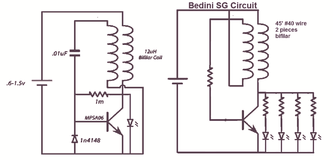
It would be beneficial to obtain schematics of the Joule Thief and Bedini oscillator circuit connections. This is an area that has not been previously explored. The schematic on the left was sourced from the Energetic Forum, while the...

Which switch mode power supply (SMPS) topology should one start with? Although the schematic of a full-bridge looks a bit complicated compared to push-pull and half-bridge designs, sticking straight to a full-bridge topology or its smaller version, the half-bridge,...
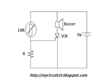
The Light Dependent Resistor (LDR) is a variable resistor whose resistance decreases as light intensity increases. Under normal light conditions, the resistance of the LDR is sufficiently high, resulting in an inadequate voltage across resistor R to activate the...
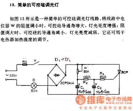
A simple silicon-controlled rectifier (SCR) dimmer circuit is depicted in Figure 13. This circuit is designed to control the brightness of lights. As the resistance in the potentiometer decreases, the conduction angle of the SCR increases, resulting in an...

The circuit described can be utilized for tossing a coin, serving as a random generator for head or tail outcomes. This circuit is applicable in various games where a coin toss is required to initiate play. It employs two...