
One of the positive and negative brake circuit to operate energy

The automatic control circuit for dynamic braking is designed to enhance the efficiency and safety of electric motor operations. The time relay (KT) serves as a critical component that determines the duration of the braking action, ensuring that the motor can decelerate smoothly without causing mechanical stress or excessive wear.
The step-down transformer (T) is employed to reduce the input voltage to a level suitable for the operation of the bridge rectifier. This transformer ensures that the rectified output is compatible with the requirements of the dynamic braking system. The single-phase bridge rectifier converts the alternating current (AC) output from the transformer into direct current (DC), which is necessary for the effective operation of the braking mechanism.
The inclusion of start (SBi) and stop (SB3) buttons allows for manual control of the braking process, enabling the operator to initiate or cease braking as needed. The reverse start (SB2) and stop buttons facilitate the operation of the motor in reverse, providing flexibility in applications where reversing the motor's direction is required.
Overall, this circuit configuration ensures a reliable and efficient method for controlling dynamic braking in electric motors, contributing to improved operational performance and safety in various applications. Circuit shown in Figure 3-144. The circuit for the automatic control of dynamic braking circuit using the time relay KT control system up time, dynamic braking power using the step-down transformer T, single-phase bridge rectifier. Figure, SBi and SB3 respectively positive start and stop button, SB2 and reverse S Island start and stop buttons.
Related Circuits
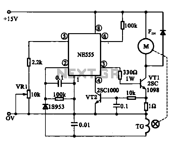
The Miniature DC Motor Speed Control circuit is designed to maintain a steady speed for micro motors, as illustrated in Figure 8-32. The circuit utilizes a voltage feedback mechanism suitable for applications such as tape recording machines that employ...
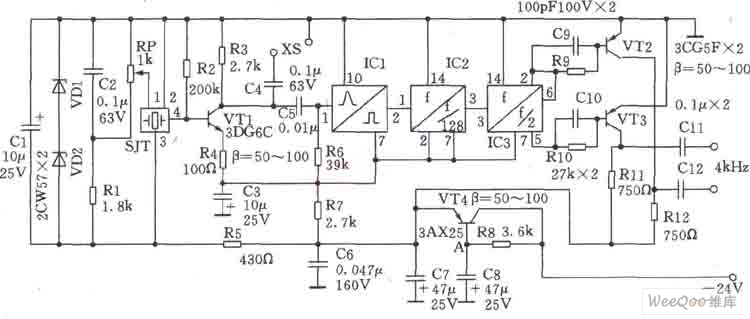
This circuit is a 1024 kHz temperature-compensated crystal oscillator. The circuit theory is illustrated. Due to the low output signal level of the circuit, a buffer using the following transistor VT1 is implemented for amplification. The base bias resistor...
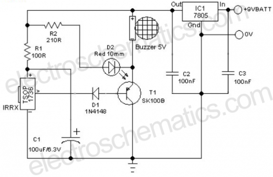
A remote-controlled alarm circuit utilizing the TSOP1736. This circuit involves routing an electric cable to connect a calling bell switch near the bed of an elderly individual. The remote-controlled alarm circuit designed with the TSOP1736 is an innovative solution for...
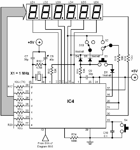
A digital audio frequency (AF) counter can be constructed using a minimal number of components by employing a single 7226B integrated circuit (IC) from Intensil, as depicted in the accompanying diagram. This circuit has an upper frequency limit of...
An amplifier is a device that accepts a varying input signal and produces an output signal that varies in the same way as the input but has a larger amplitude. The input signal may be a current, voltage, mechanical...
This circuit is an automatic street light controller. The sensor used to detect changes in light is an LDR (Light Dependent Resistor). The working principle of the LDR is that when exposed to light, its resistance value decreases, while...