
555 Negative Voltage Power Supply Circuit

The 555 timer is a versatile integrated circuit commonly used in various applications, including oscillators, timers, and pulse generators. In the context of a negative voltage power supply, the 555 timer can be configured as an astable multivibrator to generate a square wave output. This square wave can then be utilized to drive a charge pump circuit, which consists of diodes and capacitors to convert the positive voltage supply into a negative voltage output.
The charge-pump circuit operates by using the square wave output from the 555 timer to alternately charge and discharge capacitors. During the positive half-cycle of the square wave, one capacitor is charged to the input voltage. During the negative half-cycle, this charged capacitor is connected in series with the input voltage through a diode, effectively doubling the voltage across the output terminals but with an inverted polarity, thus generating a negative voltage.
Typically, the circuit will include two diodes: one for charging the capacitor during the positive cycle and another for discharging it to the output during the negative cycle. The output voltage can be further regulated using additional components, such as voltage regulators or filtering capacitors, to ensure a stable and clean negative voltage supply.
The design of this circuit allows it to be compact and efficient, making it suitable for applications where a negative voltage is required, such as operational amplifiers, analog signal processing, or powering specific sensors. Proper selection of the components, including the values of the capacitors and the specifications of the diodes, is crucial for achieving the desired output voltage and current capabilities.555 Negative Voltage Power Supply Circuit A negative supply can be generated by a ""Charge-Pump"" circuit created with a 555, diodes and.. 🔗 External reference
Related Circuits
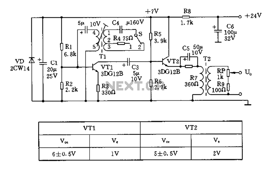
The device is designed to accelerate the defrosting process of fish, meat, and other foods by utilizing audio vibrations. This method allows for defrosting in warm water, significantly reducing the time required compared to conventional methods, while preserving the...
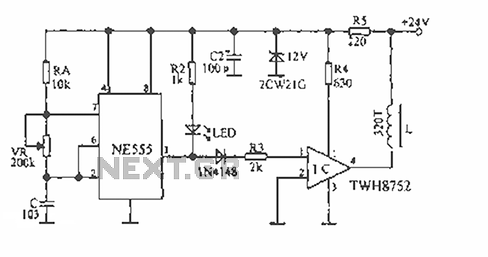
The 450/800Hz oscillation circuit depicted in the figure utilizes transformer coupling. The frequency conversion is achieved by varying the inductance through a variable filter tap (T1). When the switch control signal (S) is set to position 1, the oscillator...
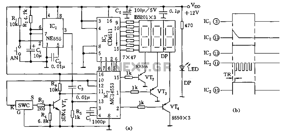
The digital thermometer consists of a temperature sensor, a single stabilizing circuit, a counter circuit, a decoding section, a driving circuit, and LED digital tubes among other components. It operates within a temperature range of 0 to 50 degrees...
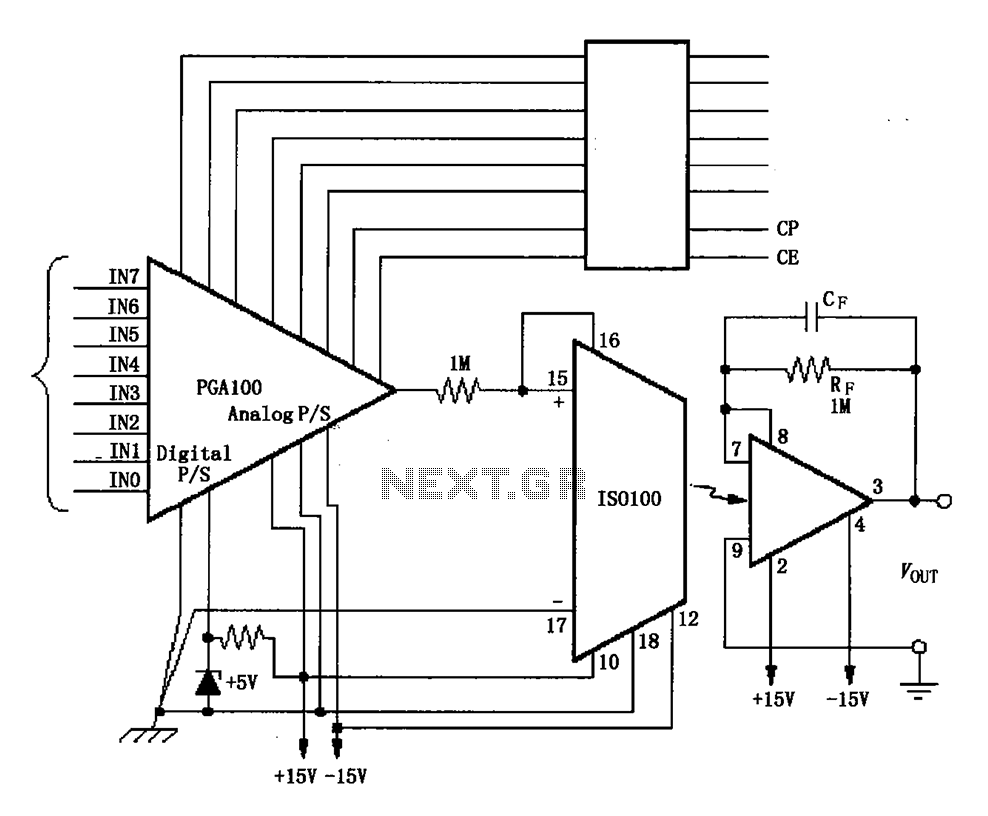
The ISO100 multichannel data acquisition system comprises a programmable gain amplifier isolated by an optocoupler, a programmable amplifier (PGA100), and an isolation amplifier (ISO100). The optocoupler selects three channels and is coupled to the programmable gain amplifier, which can...
The circuit involves powering an LED using a 3V CR2032 battery, with the intention of extending battery life by making the LED blink rather than remain continuously on. A 555 timer is considered, utilizing large value resistors in the...
The LM35 from National Semiconductor is a precision centigrade temperature sensor that provides an analog output voltage. It operates within a temperature range of -55°C to +150°C and has an accuracy of ±0.5°C. The output voltage corresponds to 10mV...