
555 Pulsing Third Brake Light Circuit

The dual 555 timer circuit operates in astable mode, generating a continuous square wave output. Each 555 timer functions independently but can be synchronized for specific applications. The circuit's frequency and duty cycle are determined by external resistors and capacitors connected to each timer.
In this configuration, the timing components for each 555 timer are typically arranged as follows: two resistors (R1 and R2) and one capacitor (C1) for the first timer, and two resistors (R3 and R4) and another capacitor (C2) for the second timer. The frequency of oscillation (f) can be calculated using the formula:
f = 1.44 / ((R1 + 2R2) * C1)
The duty cycle (D) is given by:
D = (R2 / (R1 + 2R2)) * 100%
The output from the first 555 timer can be used as the trigger input for the second 555 timer, allowing for complex timing sequences or pulse-width modulation applications. The inclusion of the 1N4148 diode may serve to protect the circuit from reverse polarity or to facilitate quick discharge paths for the timing capacitors, enhancing the reliability of the oscillation.
Overall, this dual 555 timer circuit is versatile and can be applied in various electronic projects, including LED flashers, tone generators, and other timing applications. Proper selection of the resistors and capacitors will enable fine-tuning of the output frequency and duty cycle to meet specific design requirements.The Circuit consists of two 555 timer/oscillators in a dual timer configuration both setup in unstable mode. Component: 1N4148 Diode, 555 IC, .. 🔗 External reference
Related Circuits
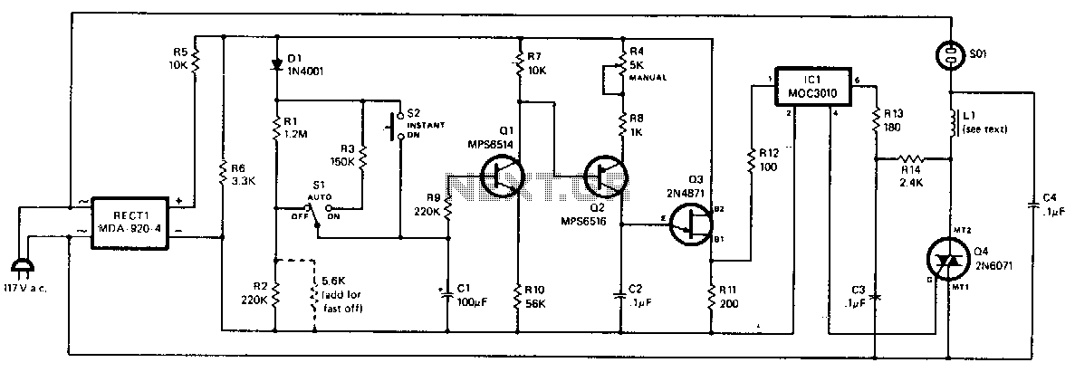
The dimming action is controlled by varying the amount of current passed through triac Q4, which in turn regulates the lamp connected to the AC receptacle. The unijunction transistor Q3 functions as a relaxation oscillator, with its output pulse...
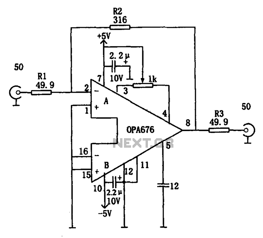
The circuit features a broadband video amplifier with a 50-ohm input/output impedance. To ensure optimal signal transmission and minimize reflected signals, it is often necessary to match the input and output impedances of the amplifier. The broadband video amplifier...
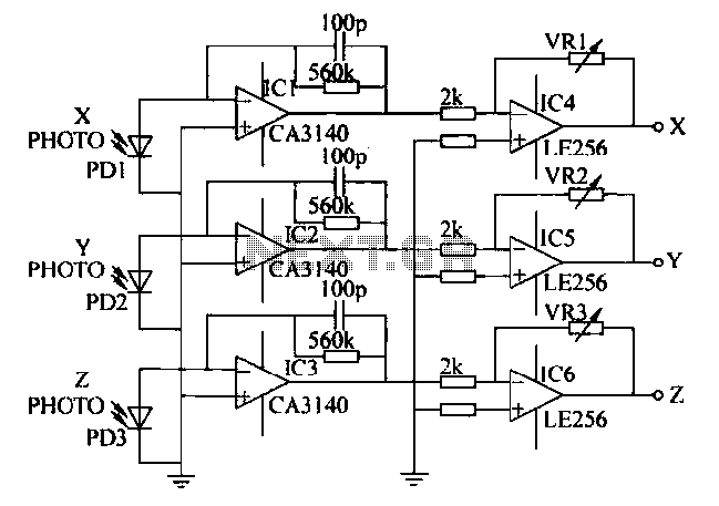
A semiconductor color sensor is designed to identify the color of an object using three photodiodes (PD1, PD2, PD3) and three corresponding color filters (X-PHOTO, Y-PHOTO, Z-PHOTO). Each photodiode is paired with a specific color filter: red (R), green...
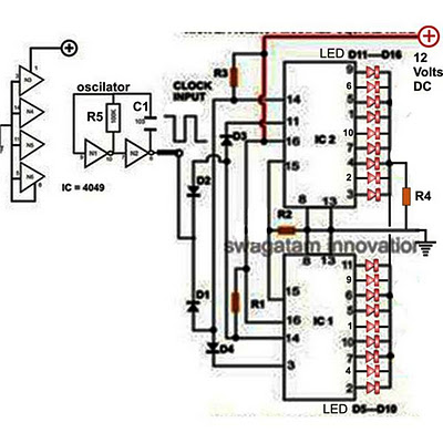
Decorative lights arranged in various moving patterns are visually appealing and have gained significant popularity in today's world. While more complex lighting arrangements may require the use of microcontroller ICs, simpler yet captivating light effects can be generated using...

The back EMF voltage spikes produced by stepper motors, especially higher voltage motors, can damage a PC's printer port if connections are made incorrectly, flyback diodes are absent, or connected in reverse. The safest options are opto-isolated or buffered/inverted...
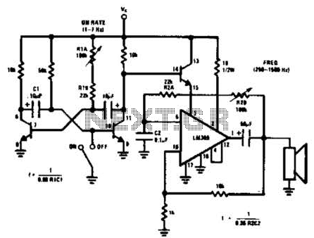
An LM380 audio IC is configured as a feedback audio oscillator. A transistor astable modulates this oscillator at a low frequency, which produces a siren tone. The circuit utilizes the LM380, a power audio amplifier IC, which is configured to...