
CoSaTrak drive satellite tracking circuit

The circuit is straightforward. The eight data output bits from a standard PC printer port are divided, with the least significant nibble controlling the four coils of the Azimuth motor and the most significant nibble controlling the coils of the Altitude motor. Each output bit connects to the base of a power transistor through a current-limiting resistor, switching it on or off based on the corresponding high or low state. Each transistor controls one coil of a motor, switching one end to ground. The other end of the coil connects to the positive motor voltage (MV), allowing current to flow when the transistor is activated, generating a magnetic field that interacts with the permanent magnet in the motor's rotor, causing it to turn incrementally until the magnetic fields align or cancel out. The computer generates the complex step patterns required for proper motor operation, and at times, multiple coils within the same motor may be energized simultaneously.
Flyback diodes are essential as they provide return paths for the high back-EMF voltages produced when a coil is switched off. Without these diodes, the transistors may fail, potentially damaging the printer port outputs. A simple power supply, consisting of a step-down transformer, bridge rectifier, and smoothing capacitor, supplies power to the motors. The transformer and bridge must be capable of handling the current drawn by four motor windings (two per motor) simultaneously. Optional components, indicated by dotted lines, can be included; if an option is not implemented, the wiring is completed directly to maintain the connection. Buffer/inverter chips can be added for enhanced protection of the printer port, and opto-isolation can provide complete electrical isolation of the external electronics. If such a chip is included, a +5V supply will also need to be added.The back EMF voltage spikes produced by stepper motors (particularly higher voltage motors) can damage your PC`s printer port if connections are made incorrectly, flyback diodes are absent or connected in reverse, etc. The safest options are opto-isolated or buffered/inverted circuits. For extra peace of mind it is recommended to rather buy a sepa rate I/O card to use instead, if your PC`s printer port is motherboard-based. Although this is very similar to Mel Bartel`s circuit, it is not an exact copy. Two main differences exist: By some strange coincidence, I just happen to choose the reverse motor order to Mel. I also did not implement the inverter/buffer stage - I am driving the transistors directly from the printer port.
A minor detail is that I seem to have chosen slightly higher rated components which could make a direct copy of my implementation slightly more expensive. Since my beta tester, Greg Roberts built a standard Bartel`s system, the CoSaTrak software was made compatible with both systems.
This means that anyone with an existing Bartel`s motorized mount can start tracking satellites straight away! Just before rushing out to witness your first high powered satellite pass, remember that the gear reductions for your astronomical requirements are quite different from the ratios needed for satellite tracking because of the different speeds involved.
Also, since I am ten years behind Mel in the development of the software, I cannot achieve the motor speeds he does with microstepping, overvoltage, etc. You will thus find that your astronomically geared mount will have quite a low limit for higher elevation passes around culmination because of the fast azimuth swings required.
Satellite imaging (as against satellite tracking) has not yet been tried with our system and it is therefore recommended to start at your lowest magnification in order to maximise the field of view. The circuit is very simple. The 8-data output bits from a standard PC printer port is split into two with the least significant nibble controlling the four coils of the Azimuth motor and the most significant nibble the coils in the Altitude motor.
Each output-bit connects to the base of a power transistor through a current limiting resistor, switching it on or off by a corresponding high or low state. Each transistor controls one coil of a motor, switching the one end to ground. Since the other end of the coil is connected to the positive motor voltage (MV), current flows when that transistor switches on, producing a magnetic field inside the motor which interacts with the permanent magnet in the motor`s rotor, causing it to turn a small amount until the magnetic fields line-up/cancel.
To make the motor turn properly the complicated step patterns required are generated by the computer and at times more than one coil in the same motor can be energised at the same time. Flyback diodes provide return paths for the high back-EMF voltages produced by switching off a coil. Without these diodes the transistors will blow and could cause this voltage to also damage the printer port outputs.
A simple power supply, consisting of a step-down transformer, bridge rectifier and smoothing capacitor supply power to the motors. The transformer and bridge must at least be able to handle the current drawn by four motor windings (two per motor) at the same time.
You might have noticed some optional components, drawn in dotted lines. In practice, when an option is not implemented, the wiring is done straight through to complete the connection. As already mentioned, the buffer/inverter chips could be added for extra protection of your printer port.
Mel even mentions opto-isolation for complete electrical isolation of the external electronics. (See Mel Bartel`s circuit page for full details. ) When such a chip is included, it would require a +5V supply which will also have to be added. The optional motor series re 🔗 External reference
Related Circuits
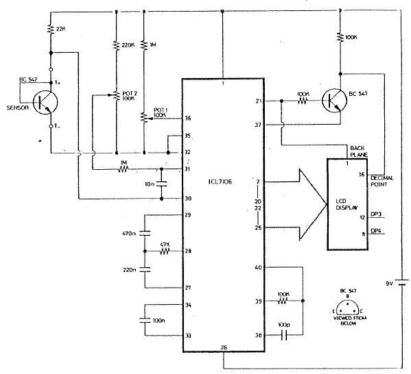
The ICL7106 integrated circuit contains all the active circuitry for a 3 1/2 digit panel meter (DPM) in a single chip. It was designed to interface directly with a liquid crystal display (LCD). The potential difference across a silicon...
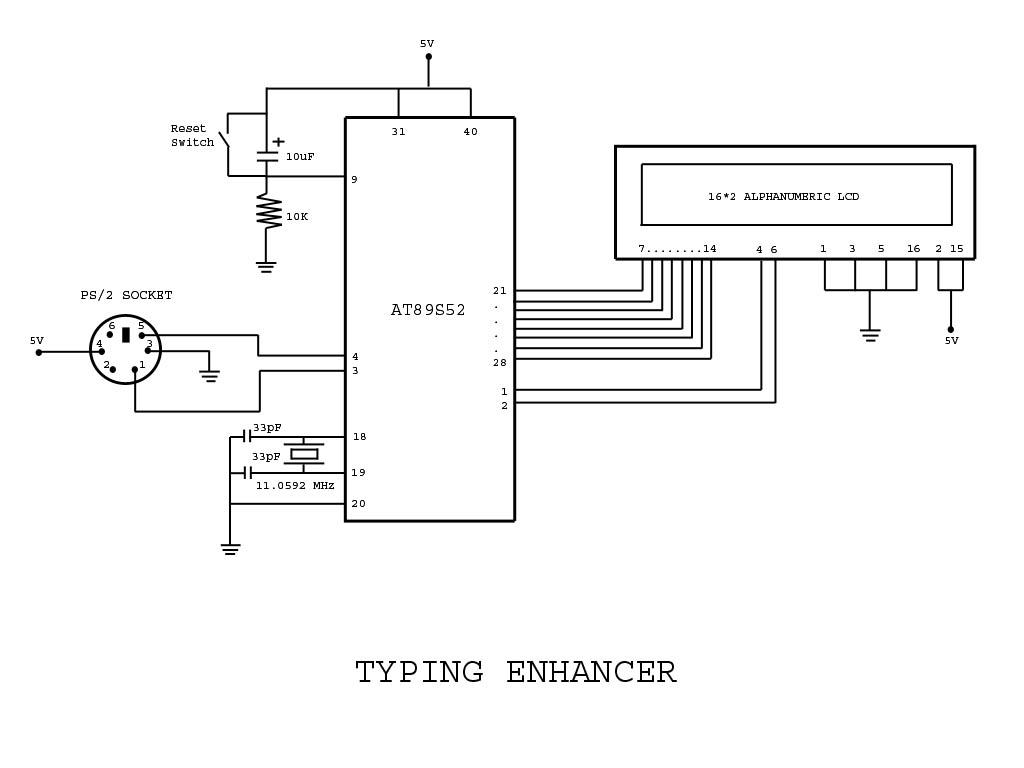
Project with Circuit and Code for a Typing Assistant using the 8051 microcontroller (AT89S52) and the PS/2 keyboard port of a computer. The project also explains the interfacing of the PS/2 port of a computer with the 8051 microcontroller. The...
The Wien-Bridge oscillator meets specific requirements due to the presence of a low-pass filter, a high-pass filter, and a 180-degree phase shift from the feedback networks connecting the input to the output. This configuration results in a total phase...
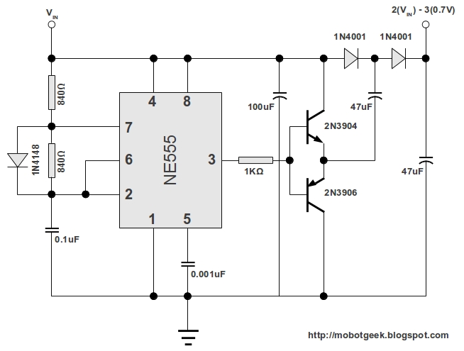
This DC voltage doubler circuit generates a voltage that is double its supply voltage. It is advantageous when a higher voltage level is required from a single lower voltage power supply. Due to the low current consumption in such...
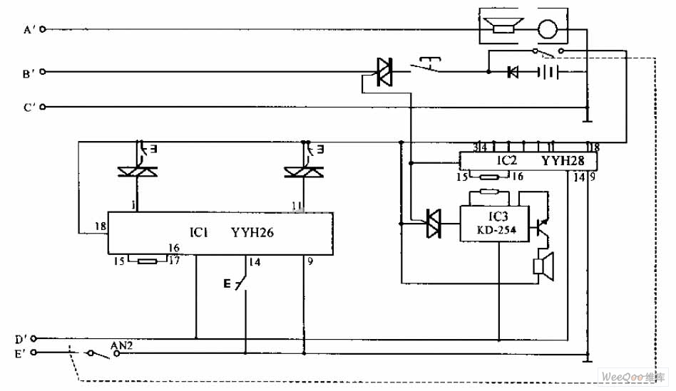
The internal telephone circuit is depicted below. By making minor enhancements to a toy telephone, it can be transformed into a functional internal telephone. This device comprises several components, including the phone unit, a decoding circuit, a ringing circuit,...
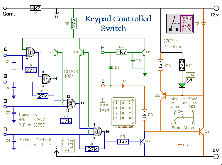
This is a universal version of the four-digit alarm control keypad. The design has been modified to free up the relay contacts, allowing the circuit to function as a general-purpose switch. A single pole changeover (SPCO) or single pole...