
555 Sawtooth Oscillator

The 555 Sawtooth Oscillator is a versatile circuit that utilizes the 555 timer IC to generate a sawtooth waveform, which is characterized by a linear rise followed by a rapid drop. This type of waveform is commonly used in applications such as audio synthesis, signal modulation, and as a timing reference in various electronic circuits.
The circuit typically operates in astable mode, where the 555 timer continuously switches between its high and low states, producing a periodic output. Key components in this configuration include resistors, capacitors, and the 555 timer itself. The frequency and duty cycle of the sawtooth waveform can be adjusted by changing the values of these passive components.
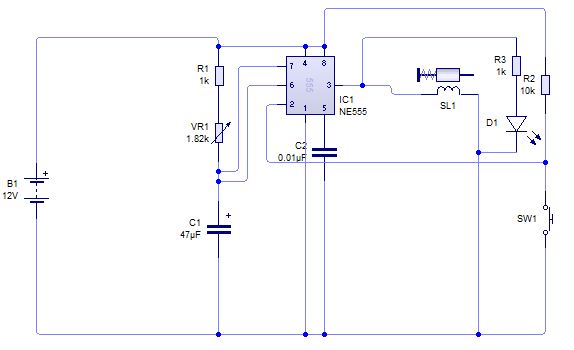
In the standard configuration, a resistor (R1) is connected between the discharge pin (pin 7) and the supply voltage (Vcc). A second resistor (R2) connects the discharge pin to the threshold pin (pin 6). A capacitor (C1) is connected from the threshold pin to ground. The output is taken from the output pin (pin 3) of the 555 timer.
During operation, the capacitor charges through both resistors, causing the voltage across it to rise linearly. Once this voltage reaches approximately two-thirds of the supply voltage, the 555 timer resets, discharging the capacitor rapidly and causing the output to drop. This cycle repeats, generating the sawtooth waveform.
The frequency of oscillation can be calculated using the formula:
\[ f = \frac{1.44}{(R1 + 2R2) \times C1} \]
Where:
- \( f \) is the frequency in hertz (Hz),
- \( R1 \) and \( R2 \) are the resistances in ohms (Ω),
- \( C1 \) is the capacitance in farads (F).
The duty cycle, which defines the proportion of time the output is high versus low, can also be adjusted by varying the resistor values. A lower R2 value results in a higher duty cycle, while a higher value decreases it.
This circuit can be simulated using various electronic circuit simulators, allowing users to visualize the waveform and make adjustments to component values in real-time. This feature aids in understanding the behavior of the sawtooth oscillator and its applications in different electronic systems.This is the 555 Sawtooth Oscillator circuit diagram with the detailed explanation of its working principles. The electronic circuit simulator helps you to design the 555 Sawtooth Oscillator circuit and to simulate it online for better understanding..
🔗 External reference
Related Circuits
A circuit is being designed to trigger solenoid valves for airbags in a car, requiring a time range of 0 to 1 second. The selected valves operate at 12V, 0.5A, and can activate within a maximum speed of 200...
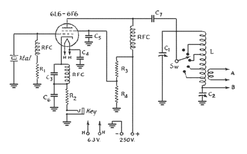
An oscillator-only transmitter appears to be the simplest way to access the radio airwaves; however, it presents several challenges as part of a transmitting and receiving station. The issue of finding an adequate crystal-controlled transmitter for newcomers wishing to...
The capacitor charges until the switching voltage is reached. When the switch (SUS) is activated, the inductor causes the current to oscillate. When the current through the switch drops below the holding current, the device turns off, and the...
A question has been raised regarding the type of oscillator found on Wikipedia, specifically referring to the NPN Colpitts oscillator as illustrated in the image titled "File:NPN Colpitts oscillator collector coil.png." The NPN Colpitts oscillator is a type of electronic...

There are three oscilloscopes currently available: an older optoelectronics Opto-7000 that is rarely used, a newer Mitronics MIC-1028, and a recently acquired used Tektronics 2236 oscilloscope purchased at Dayton in 2009, which features a built-in frequency counter. During a...

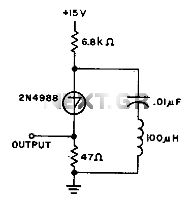
One of the simplest methods of metal detecting is through a beat frequency oscillator. The circuit consists of two balanced oscillators: one provides a reference signal, while the other acts as the detector element. The frequency of the reference...