
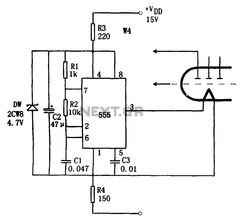
555 simple electronic keyboard circuit

The controllable multivibrator circuit utilizes the 555 timer in an astable configuration, allowing it to generate a continuous square wave output. The frequency of the output waveform is primarily determined by the values of the resistors RA and RP1, as well as the capacitor C1. The control voltage at pin 5 plays a significant role in modulating the frequency of oscillation. By adjusting the voltage at this pin, the duty cycle and frequency can be altered, providing a means for external control over the timing characteristics of the circuit.
Resistors R1 to Rn and RB form a voltage divider network, influencing the voltage level seen at pin 5. The conduction state of the transistor VT1 further modifies this voltage, as it can either allow or block current flow, thereby affecting the voltage divider's output. When VT1 is in the active region, it allows the control voltage to rise or fall depending on the input signal, thereby dynamically adjusting the frequency of oscillation.
The output from the 555 timer can be used to drive various loads or can be fed into additional stages for further signal processing. This multivibrator configuration is widely used in applications such as pulse width modulation, tone generation, and timing circuits, making it a versatile component in electronic design. The careful selection of component values and the configuration of the circuit will determine the performance characteristics, such as frequency range and stability, making it essential to consider these factors during the design process.As the figure 14-40 shows, the controllable multivibrator is composed of the 555 and RA, RP1, C1, the oscillation frequency is related with the control voltage (pin-5), but the voltage of pin-5 depends on the partial voltage of R1?Rn and RB, and it is related with the conduction situation of VT1. The VT1 works in the amplifier region, voltage of electrode c.. 🔗 External reference
Related Circuits
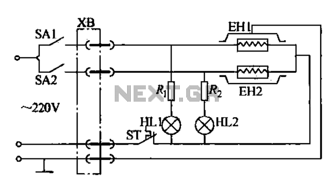
Currently, the use of cookers has become fashionable due to their speed, cleanliness, and low pollution levels, making them a favorite among consumers. Cookers circuit. The modern cooker circuit typically involves a combination of heating elements, control systems, and safety...
The Zener diode may not be providing sufficient current in its breakdown state to activate the transistor. Removing resistor R2 did not resolve the issue. The Zener's voltage selection could be too high, potentially preventing it from regulating the...
The thermocouple cold junction compensation circuit and the MAX6675 converter circuit diagram form a temperature measuring system. The system utilizes a K-type thermocouple connected to the T terminals of the MAX6675, with the cold junction grounded. An 8051 microcontroller...

In a panic situation during the night when an intruder attempts to break into a house, this alarm system will assist by emitting a loud police siren to deter the intruder. The alarm system is designed to enhance home security...
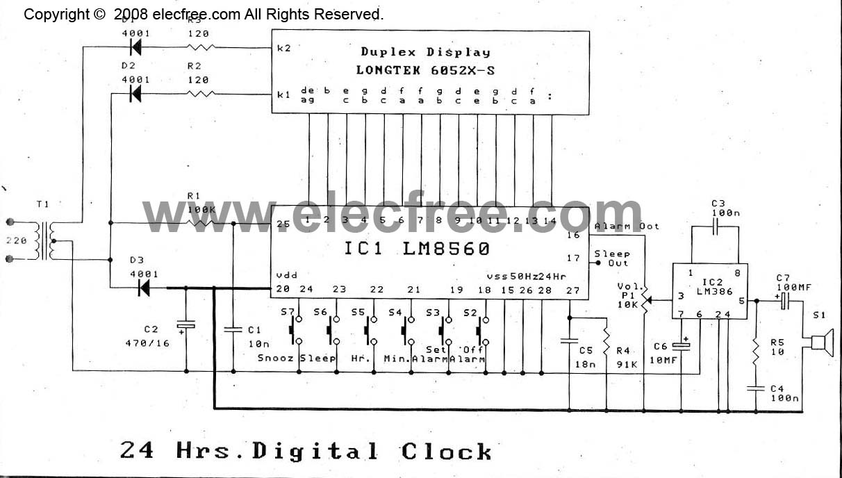
The digital time clock circuit is of great interest to electronic amateurs. The most popular clock ICs include the LM8361 and MM5387. Unfortunately, these ICs... The digital time clock circuit serves as an essential component for various electronic applications, providing...
The economic fluorescent display circuit is illustrated in the figure. The primary component of this circuit is the 555 timer configured as a multivibrator. The oscillation frequency is determined by the components R1, R2, and C1, with a frequency...