
Cheap fluorescent display circuit 555

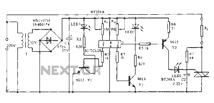
The economic fluorescent display circuit utilizes a 555 timer integrated circuit (IC) configured in astable mode, which generates a square wave output. The frequency of oscillation is primarily influenced by the resistors R1 and R2, and the capacitor C1. The relationship of the frequency can be expressed mathematically as f = 4/(R1 + 2R2) C1, which allows for fine-tuning of the output frequency to approximately 4 kHz. This frequency is suitable for driving the fluorescent display effectively.
The circuit includes a filament biasing arrangement, where the voltage across the filament is determined by the resistor divider formed by R3 and R4. The voltage VDD is calculated as VDD = R4/(R3 + R4) * V_supply, ensuring that the filament operates at the required 6V for optimal performance.
To drive the fluorescent charactron, the circuit can accept a peak-to-peak DC voltage (Vp-p) and an AC voltage in the range of 4V to 6V. This capability allows for the efficient operation of the fluorescent display, which is essential for visual output in various applications. The simplicity of the circuit design, coupled with the availability of common electronic components, makes it an attractive choice for manufacturers and hobbyists alike. The ease of assembly and low cost further enhance its practicality in electronic display systems. As shown in FIG economic fluorescent display circuit. The core of the circuit is the multivibrator 555 and R1, R2, C1 and other components of the oscillation frequency is f 1.4 4/(R1 + 2R2) C1, the icon parameter corresponding frequency of approximately 4kHz. FIG filament DC bias of VDD R4/(R3 + R4) F 6V. This circuit can be coupled with a DC voltage Vp-p and a voltage of about 4V 6V AC voltage to the fluorescent nkHz charactron filament calculator, so that the fluorescent charactron work displayed. The circuit configuration is simple and easy to manufacture.
Related Circuits
The built-in temperature sensor is utilized to control the triac TC620 for temperature regulation. The adjustment circuit, consisting of resistors Rp1 and Rn, allows for modifications to the lower temperature limit. When the ambient temperature exceeds this lower limit,...
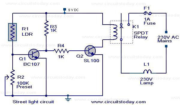
A street light that automatically switches ON when night falls and turns OFF when the sun rises. The circuit uses an LDR to sense the light. The automatic street light circuit functions by utilizing a Light Dependent Resistor (LDR) as...

This circuit utilizes a pair of Zener diodes to monitor the voltage of a 12-V battery. When the voltage drops below 11 V, diode D1 ceases to conduct, causing pin 3 of flip-flop IC2 to go high. This action...
The circuit operates on the principle of detecting smoke produced during a fire, which passes between a light bulb and a light-dependent resistor (LDR). As smoke obscures the light, the amount of light reaching the LDR decreases, resulting in...
The circuit consists of inverter and charger sections. The inverter section utilizes the NE555 timer, while the charger section is based on the LM317 adjustable regulator. In the inverter section, the NE555 is configured as an astable multivibrator, generating...
This circuit is primarily designed to provide a microphone input for standard home stereo amplifiers. Utilizing a battery supply effectively eliminates the risk of low-frequency hum interference from mains power, simplifying the connection to the amplifier by removing the...