
555 timer as a voltage to frequency converter

The project involves designing a circuit that takes a direct current (DC) voltage input ranging from 0 to 10 volts and converts it into a square wave output with a frequency that varies linearly with the input voltage. This type of circuit is commonly used in applications such as signal modulation, control systems, and frequency generation.
To achieve this, a voltage-controlled oscillator (VCO) can be employed. The VCO will generate a square wave output whose frequency is directly proportional to the input voltage. The circuit can be designed using operational amplifiers (op-amps) and other discrete components.
The primary components of the circuit include:
1. **Input Stage**: This stage will include a voltage divider or buffer to ensure that the 0-10V input signal is properly conditioned for the VCO.
2. **Voltage-Controlled Oscillator (VCO)**: A VCO can be implemented using an op-amp configured in a relaxation oscillator configuration. The frequency of oscillation can be set by selecting appropriate resistor and capacitor values in the feedback loop.
3. **Output Stage**: The output square wave can be further processed or buffered to match the desired load or interfacing requirements.
The frequency range of the output square wave should be carefully calculated based on the specifications of the project. For instance, if the requirement is to achieve a frequency range from 1 Hz to 10 kHz with a 0-10V input, the values of the resistors and capacitors in the VCO circuit must be chosen accordingly to ensure the linear relationship between input voltage and output frequency.
Additional considerations include power supply decoupling, signal integrity, and potential filtering to eliminate any unwanted harmonics or noise from the square wave output. Proper simulation and testing of the circuit will be essential to validate performance before final implementation.Hi All, I am currently working on a project that requires a 0-10V DC supply to be converted into a linear fequency range - square wave. for instance.. 🔗 External reference
Related Circuits
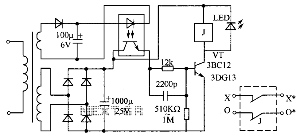
The circuit protection mechanism utilizes optocouplers for on-off control. Under normal voltage conditions, the output from the optocouplers is minimal, and the VT transistor operates in reverse bias. However, if the circuit voltage increases due to reasons such as...

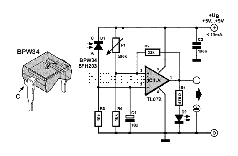
This device is designed to be a simple, inexpensive comparator intended for use in a solar cell power supply setup where a quick "too low" or "just right" voltage indicator is needed. The circuit consists of one 5V regulator,...

In some cases, it is necessary to power a circuit from a battery, where the required supply voltage falls within the battery's discharge curve. A new battery provides a higher voltage than needed, while a battery nearing the end...
The Maya utilized several calendars concurrently, one of which is known as the "long count." This calendar is a continuous record of days starting from a zero date that corresponds to August 13, 3114 BC. According to the Maya...
How to change the brightness of an LED. Are LED lights dimmable? Is it possible to adjust the brightness of LEDs? An LED is essentially a diode; when the forward voltage exceeds 0.7 volts, it begins to emit light,...
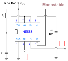
The 555 Timer is an integrated circuit utilized for various functions such as timing, pulse generation, and tone generation, all from a single universal IC. Each pin's function is detailed, and design recommendations are provided as necessary. A Monostable...