
Overvoltage protection circuit diagram

The described circuit protection system is designed to safeguard electrical devices from overvoltage conditions by utilizing an optocoupler-based control mechanism. The optocouplers serve as a critical interface that isolates the high-voltage side of the circuit from the control logic, ensuring safety and reliability. Under normal operating conditions, the optocoupler remains inactive, keeping the VT transistor in a reverse-biased state, which prevents current flow through the relay and maintains the circuit in a safe state.
In the event of an overvoltage situation, the secondary voltage detected by the sampling circuit activates the optocoupler, which in turn increases the output current. This change in output current raises the bias voltage at the base of the VT transistor, driving it into saturation. As the VT transistor conducts, it energizes the relay coil. The relay contacts then open, effectively disconnecting the power supply to the load, thus providing immediate protection against potential damage.
Once the overvoltage condition is resolved, the circuit is designed to automatically reset. This feature is crucial for maintaining operational continuity without the need for manual intervention. The LED indicator integrated into the circuit provides a visual cue of the circuit's operational status, signaling whether the system is in a protected state or if a fault condition has occurred.
Component selection plays a vital role in the circuit's performance. The optocouplers, such as the 4N25, are chosen for their reliable switching characteristics and isolation capabilities. The selected triode, either the 3BG12 or 3BG13, is capable of handling the necessary current and voltage levels required for effective operation. The relay must have contacts rated for at least 5A to ensure it can handle the load current safely. Furthermore, the coil voltage of the relay can be customized to fit the application's requirements, allowing for flexibility in design.
The power transformer is specified to have a primary voltage rating of 380V, calculated based on the maximum RMS voltage. This ensures that the system can operate correctly under normal conditions without exceeding the voltage ratings of the components involved. The rectifier circuit should be designed according to the specific requirements of the application, ensuring that it can handle the expected load and provide stable DC output.
In summary, this circuit protection design effectively utilizes optocouplers and relays to ensure the safe operation of electrical devices, providing a robust solution against overvoltage conditions while allowing for automatic reset functionality and visual indication of the system status. As shown in FIG circuit protection circuit is the use of optocouplers or not the on-off control. Voltage is normal, almost no output optocouplers, VT pipe is reverse biased and off. For some reason when the circuit voltage rises (zero line break or wrongly connected to the zero line phase lines, etc.), along with increased secondary voltage sampling circuit, the optocoupler operating conditions are met. Optocoupler output current increases, the bias voltage is increased and the tube VT saturated conduction, the actuator relay pull, turn off the power to protect electrical purposes.
If the fault is eliminated, along with normal voltage, the circuit out of service immediately, recovery circuitry.Component selection: Used optocouplers 4N25 or similar goods. Triode tube 3BG12 rate with *** or 3BG13 can. Relay contacts use 5A or more. Coil voltage can be customized (5V to more than tens of volts can be). Do continued flow tube with a light emitting diode LED, doubles as an indicator. We need to change hands is the power transformer primary 380V calculated according to the maximum (here by the primary 380V RMS calculation), which ensures that once the phase voltage equal to line voltage, the device can work normally they would not damage the secondary voltage according to the relay coil determining the operating voltage, the rectifier circuit can refer to the specific requirements of the technical requirements.
Related Circuits
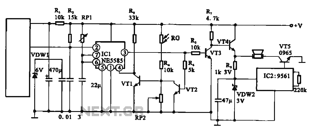
This circuit illustrates an automatic unattended burglar alarm system designed primarily for residential use, warehouses, and similar applications. The circuit features a pyroelectric infrared sensor integrated with a light control mechanism. It comprises components such as resistors (RG, RP2,...
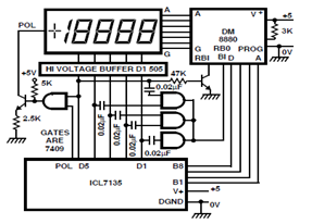
A circuit diagram for driving a plasma-type display using the ICL7135 is presented in the schematic. This application highlights the versatility of this integrated Analog to Digital Converter device. The ICL7135 is a high-precision, low-power, integrating Analog to Digital Converter...
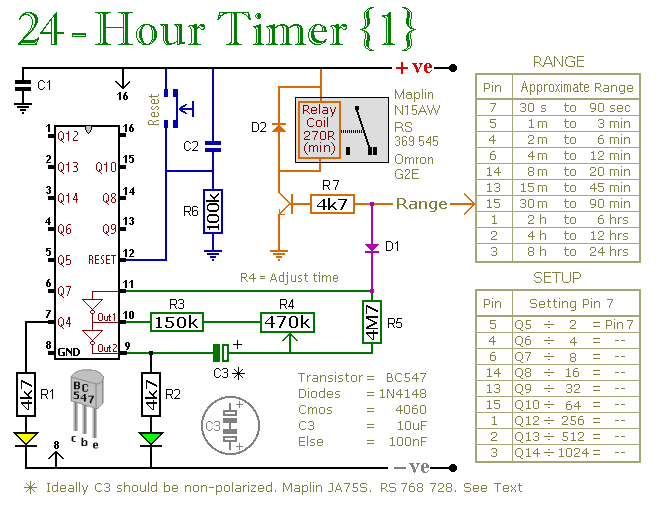
A pair of multi-range timers that provide timing periods extending up to 24 hours and beyond. Both timers are fundamentally identical, with the primary distinction being their relay behavior upon the completion of the timing cycle. Version 1 activates...
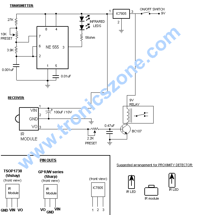
The circuit employs a widely used Sharp IR module (the Vishay module may also be utilized). The pin numbers indicated in the circuit pertain to both the Sharp and Vishay modules. For other modules, it is recommended to consult...
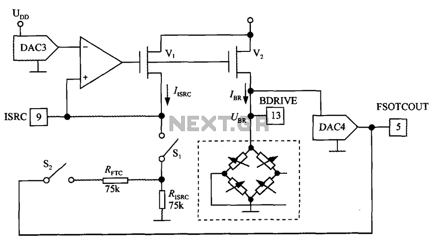
The excitation circuit for the digital pressure signal conditioner MAX1458 is illustrated. The output DAC3 is utilized to adjust the sensor excitation current (IBR), enabling full-scale fine calibration. The reference current (IISRC) is determined by the resistor RISRC and...
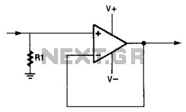
An operational amplifier (op amp) can function as a unity gain amplifier by connecting its output to its inverting input as illustrated. The load resistance (Rl) should be sufficiently low to prevent the op amp's bias current from introducing...