
555 Timer astable oscillator circuit

The 555 timer is a versatile integrated circuit used in various timing applications, including oscillators, pulse generation, and time delay circuits. In this configuration, the circuit operates in astable mode, producing a continuous square wave output. The independent time constants, defined by the resistors (R) and capacitors (C), determine the duration of the high and low states of the output signal.
The first time constant, 1.1RcC2, represents the time taken for the capacitor C2 to charge through the resistor R, reaching approximately 66.7% of the supply voltage (Vcc). Conversely, the second time constant, 1.1RcC3, reflects the time taken for the capacitor C3 to discharge through the same resistor R, dropping to about 33.3% of Vcc. The independence of these time constants allows for flexible control over the duty cycle of the output waveform.
The free-running period (th) of the 555 timer in this configuration is the sum of the two time constants, which can be expressed mathematically as:
th = 1.1RcC2 + 1.1RcC3.
This relationship is critical for applications requiring precise timing and control, as it allows for the adjustment of the frequency and duty cycle by varying the values of the resistors and capacitors. By selecting appropriate component values, designers can tailor the output waveform to meet specific requirements, making the 555 timer an essential tool in electronic circuit design.555 timer circuit unsteady open and closing times are independent of each other. Wherein a time constant is 1.1RcC2, another time constant is 1.1RcC3. Free-running period is th e sum of these time constants.
Related Circuits
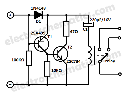
This low current relay circuit is designed for use in battery-operated electronic devices. Its operating current is in microamperes (µA). This is achieved by using a bistable relay and incorporating additional components to enable the relay to function like...
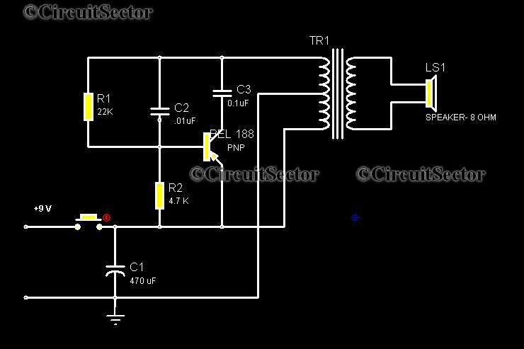
This circuit is a low-cost, one-touch doorbell using a Bel 188 transistor. It is likely one of the most economical bell circuits that can be constructed. The core component of this circuit is the output transformer from a push-pull...
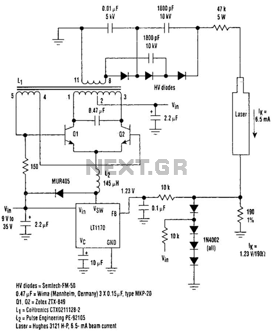
Driving Helium-Neon lasers can be greatly simplified using this power supply configuration. When power is applied, the laser does not conduct, and the voltage across the 190-ohm resistor is zero. However, a resonant circuit and a voltage tripler then...
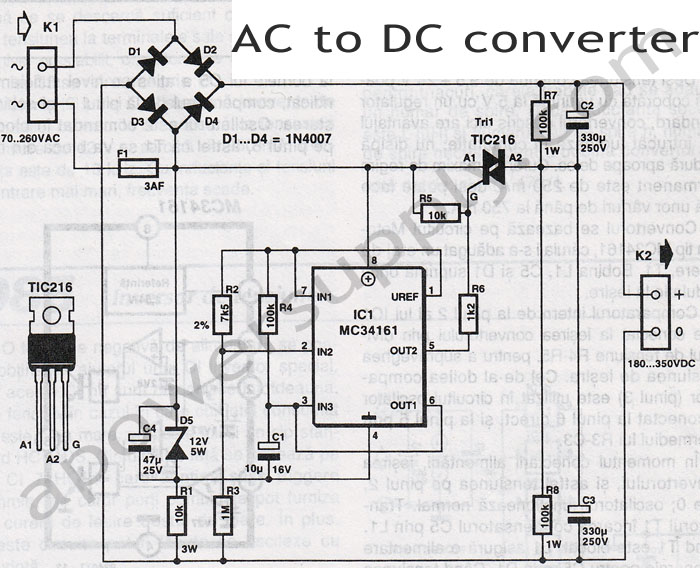
This voltage-to-frequency converter circuit features a voltage-controlled oscillator with a deviation of 0.5%. The integrated circuit IC1 functions as a multivibrator, generating rectangular impulses of equal width. The output frequency is adjustable via the U1 voltage. The D3 diode...
The CXA1600M and CXA1600P are 8-pin single-chip bipolar integrated circuits (ICs) designed for AM radios. These ICs encompass all necessary functions from the front-end to the power amplifier, eliminating the need for external filters, which makes the attachment of...

This circuit is used for a Digital Radar Speedometer. It allows for the measurement of the speed of any moving object, particularly vehicles such as cars. The speed is displayed in kilometers per hour (KPH) with a three-digit display....