
Control Circuits

The low current relay circuit is particularly suitable for applications where power efficiency is critical, such as in portable devices powered by batteries. The bistable relay allows the circuit to maintain its state without continuous power, significantly reducing the overall current consumption. By integrating additional components, such as resistors and capacitors, the relay can be configured to respond to input signals in a manner similar to a monostable relay, providing a temporary output state before returning to its default state.
The wireless keylogger project is designed for ease of assembly and use. The logging unit captures keystrokes and transmits the data wirelessly to the USB receiver, which connects to a host computer. The 2.4GHz frequency band is chosen for its balance of range and interference resistance, making it suitable for indoor applications. The keylogger's firmware is programmed to handle data encoding and transmission, ensuring that keystrokes are logged accurately and efficiently.
The PCB design is optimized for compactness and functionality, allowing for easy integration into various devices. The project documentation includes detailed schematics that illustrate the connections between components, as well as layout designs for manufacturing the printed circuit board. The software provided enables users to configure the keylogger settings and retrieve logged data from the receiver.
Overall, this combination of a low current relay circuit and a wireless keylogger presents a versatile solution for applications requiring discreet monitoring and efficient power usage. The design and implementation details provided in the project documentation facilitate successful replication and deployment of the system in various electronic devices.This low current relay circuit is designed to be used in battery operated electronic devices. Its operating current is in micro amperes ( µA). This is done by using a bistable relay and adding some components to force the relay to behave like a monostable relay. Read more » This is a do it yourself wireless hardware keylogger project, consisting of a logging unit with a 2. 4GHz transmitter, and a USB-based receiver. The project includes the schematics, PCB design, firmware, software and lots of additional files and data. A wireless keylogger is a perfect solution for monitoring user activity, at very low risk of disclosure, is a purely electronic device, so no access to the operating system is required.
The Wireless Keylogger consists of two main building blocks: the transmitter, and the receiver. The actual keylogging takes place in the transmitter, which is in fact a PS/2 hardware keylogg. Read more » 🔗 External reference
Related Circuits
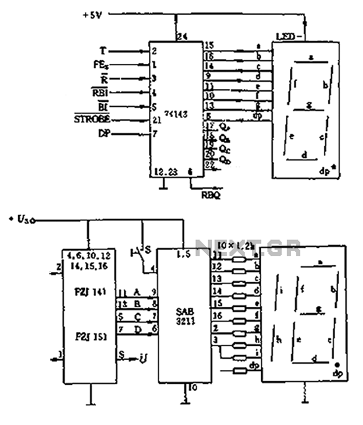
The decimal seven-segment storage decoding drive unit 74HC143 provides a constant output for all segments, each at a voltage of 5V and a current ranging from approximately 15mA to 22mA. The BCD data for the seven-segment decoder can be...
A schematic diagram of the remote-control receiver is presented. The core component of the circuit is IC1, a PIC16C54 8-bit CMOS microcontroller produced by Microchip. The microcontroller retains its data in IC2, a 93LC46 1-kbit serial EEPROM (electrically erasable...
This circuit leads palmorefmata coils, engine. Each coil is driven by a transistor type Darlington. Darlington Transistors internally comprise two transistors connected in series. The "hfe" Darlington is equal to the multiplication of "hfe" of both its internal transistor....
.jpg)
This is a general-purpose remote control project utilizing programmable PIC microcontrollers (PIC16F628, PIC16F630, PIC16F684). Schematics are provided for using infrared (IR) or radio frequency (RF) media. For those unfamiliar with microcontroller programming, fixed encoder and decoder integrated circuits can...
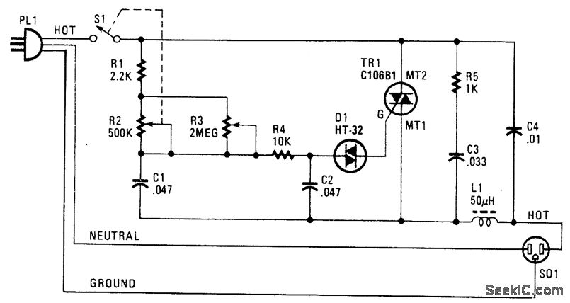
The following circuit illustrates a Phase Controlled Triac (HT-32) Circuit Diagram. Features include a simple circuit design, and bilateral triggering diacs provide a... The Phase Controlled Triac circuit, utilizing the HT-32 component, is designed for applications requiring precise control of...
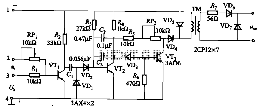
The circuit is designed for inductive loads, specifically within a thyristor power unit, such as a three-phase step-down DC motor speed control and other applications. It is capable of delivering sufficient output power to trigger a thyristor rated at...