
555 timer circuit

The NE555 timer is widely used for generating precise time delays and oscillations in various applications. In this specific configuration, it operates in monostable mode, where the output pulse duration is determined by the resistors and capacitor connected to it.
In the ten-minute timer circuit, the timing interval is set by selecting appropriate resistor (R1) and capacitor (C1) values. The relationship between the timing components and the output duration can be expressed by the formula:
\[ T = 1.1 \times R1 \times C1 \]
Here, T is the time in seconds, R1 is the resistance in ohms, and C1 is the capacitance in farads. For a ten-minute timer, R1 and C1 must be chosen carefully to meet this requirement.
Typically, a push-button switch is connected to the trigger pin of the NE555. When the switch is pressed, it sends a low signal to the trigger pin, causing the output pin to go high for the duration of the timing interval. Once the time elapses, the output returns to a low state.
Additionally, a diode may be included in the circuit to prevent any back-emf that could disrupt the timing process when the switch is released. The circuit may also incorporate an LED indicator connected to the output pin to visually signal when the timer is active.
Power supply requirements for the NE555 timer generally range from 4.5V to 15V, allowing for flexibility in various applications. Proper decoupling capacitors should be placed near the power pins to stabilize the voltage and reduce noise.
In summary, this ten-minute timer circuit utilizing the NE555 timer is a practical and widely applicable design that showcases the versatility of the 555 IC in timing applications.The schematic shown below is a 555 timer circuit. NE555 is a famous IC comes in 8 pin dip plastic package. There is a huge list of 555 IC circuits due to which this IC is very popular among electronics hobbiests, students and experimenters. The circuit mentioned here is a ten minutes timer, after pusing 🔗 External reference
Related Circuits
This circuit is designed for children's entertainment and can be installed on bicycles, battery-powered cars, motorcycles, as well as on models and various games and toys. When switch SW1 is positioned as depicted in the circuit diagram, it generates...
This is a digital dice circuit that uses the PIC16C84. The digital dice circuit utilizing the PIC16C84 microcontroller is designed to simulate the random rolling of a standard six-sided die. The circuit operates by generating a random number between 1...
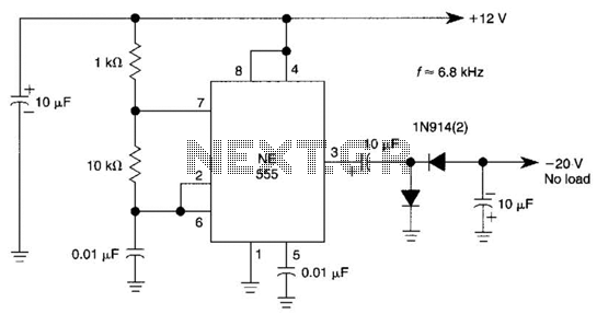
This DC negative-voltage generator based on the 555 produces a negative output voltage equal to approximately 2 times the DC supply voltage. The described circuit utilizes the popular 555 timer IC configured in an astable or monostable mode to generate...
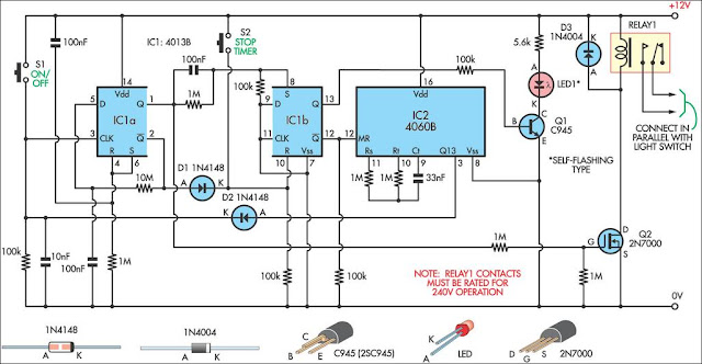
This 9-minute timer switch is designed to control lighting in a toilet or bathroom. The timer is activated by pressing switch S1 and deactivated by pressing S1 again. If the switch is not turned off, the light will automatically...

Any NPN transistor can be used. The author used a 2N3904, but a 2N2222A should work just as well. A good, low noise transistor would be even better. Some radios only have three connections to their ferrite bar antenna:...
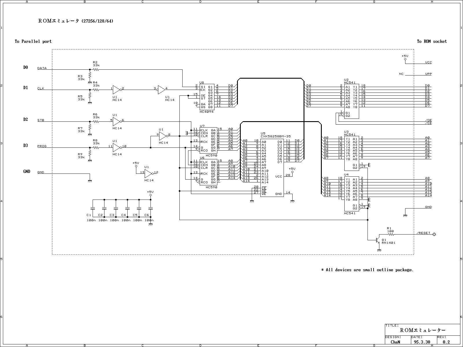
This ROM emulator improves the easiness to build/use it by reducing down its function which can be used as a ROM emulator. The kind of the ROM types to be emulated are 2764, 27128, and 27256. The debugging capability...