
555 timer Door minder electronic project circuit diagram

The door minder project employs a 555 timer IC configured in a monostable mode, ensuring that the relay remains energized while the IR beam is intact. The IR transmitter typically consists of an IR LED that emits a continuous beam, while the IR receiver includes a photodiode or phototransistor that detects the presence of the beam. The design allows for a robust detection range, making it suitable for various applications, including security systems and automated entry alerts.
The circuit requires a stable 12V DC power supply to function correctly. Upon powering the circuit, the 555 timer's output pin is connected to the relay's coil, allowing the relay to close its contacts and activate the connected bell or alarm when the IR beam is uninterrupted. The capacitor in the circuit serves as a timing element, ensuring that the relay remains activated for a predetermined duration even after the beam is momentarily interrupted.
To enhance the reliability of the system, it is advisable to incorporate a resistor-capacitor (RC) filter at the output of the IR receiver to eliminate noise and false triggering. Additionally, the circuit can be fine-tuned by adjusting the values of the resistor and capacitor associated with the 555 timer to modify the response time and sensitivity of the system.
In conclusion, this door minder electronic project effectively utilizes a 555 timer circuit and an IR beam for monitoring entry points, providing a practical solution for detecting movement in a specified area while ensuring ease of installation and operation.This door minder electronic project is based on a 555 timer circuit and uses an IR beam to monitor door and passage-ways or any other area. When the IR beam is broken a relay is tripped which can be used to sound a bell or alarm. This door minder electronic project is suitable for detecting customers entering a shop, cars coming up a driveway, etc
. Because the IR beam is very strong distances over 25 yards can be monitored with electronic circuit. The receiver module consists of an IR receiver module that detects the incoming beam from the transmitter. The IR signal is used to keep a capacitor charged which in turn holds a relay operated. When the beam is broken the capacitor discharges and the relay releases. This circuit must be powered from a 12volt DC supply. 🔗 External reference
Related Circuits

Carrier current remote control device or intercom circuit diagram as follows: The circuit diagram for a carrier current remote control device or intercom system typically involves the use of carrier current technology to transmit audio signals over existing electrical...

A small biped walker constructed from 2mm plywood, powered by two RC servos. It utilizes the widely available and programmable flash microcontroller PIC16F84. This simple circuit is designed to program the PIC16F84 and similar flash memory components. The project...
It utilizes the mains supply through a basic DC rectifier circuit. The circuit operates by converting alternating current (AC) from the mains supply into direct current (DC) using a rectifier. A typical implementation involves a bridge rectifier configuration, which consists...
Chevy S-10 Blazer Ignition Control (IC) Circuit Wiring Diagram. The Chevy S-10 Blazer ignition control circuit is a critical component in the vehicle's ignition system, responsible for managing the timing and operation of the engine's spark plugs. The circuit typically...

It is possible to add bus masters to the system, but a different bus architecture would be required since the Integrator/CP uses the AHB-Lite bus protocol, which allows only one bus master (the ARM CPU core). One way to...
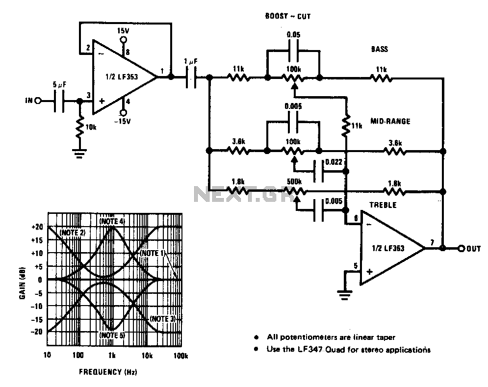
A simple single-transistor circuit provides an approximate 15 dB boost at 100 Hz and a 15 dB cut at 15 kHz. A low-noise audio transistor is utilized, and the output can be directly connected to any existing amplifier volume...