
Carrier current remote control device or intercom circuit diagram

The circuit diagram for a carrier current remote control device or intercom system typically involves the use of carrier current technology to transmit audio signals over existing electrical wiring. This system allows for communication between different points without the need for dedicated wiring, utilizing the electrical infrastructure already in place.
The primary components of this circuit include a microphone, an audio amplifier, a modulator, and a demodulator. The microphone captures the audio input, which is then amplified by the audio amplifier to ensure sufficient signal strength. The modulator converts the audio signal into a high-frequency carrier wave suitable for transmission over the electrical lines.
The carrier wave is then sent through the power lines, where it can travel to various locations within the building. At the receiving end, the demodulator extracts the audio signal from the carrier wave, allowing it to be played back through a speaker or another audio output device.
Additional components may include filters to reduce noise and improve signal clarity, as well as power supply circuits to ensure the system operates efficiently. The design must also consider impedance matching to optimize the transmission of audio signals and minimize signal loss.
This type of intercom system is particularly advantageous in residential or commercial settings where installing new wiring is impractical. By leveraging existing electrical infrastructure, carrier current intercom systems provide a cost-effective and efficient solution for communication needs. Carrier current remote control device or intercom circuit diagram as follows:
Related Circuits
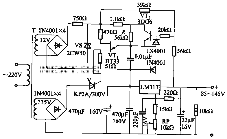
It utilizes a three-terminal adjustable voltage regulator power supply and incorporates a thyristor for presetting the LM317. The voltage can be adjusted between 85V and 145V, with an output current limited to a maximum of 1A. An adjustment potentiometer...
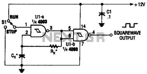
Two gates of the Quad 4093 are utilized to create an oscillator. The resistor (R) can range from approximately 5 kΩ to around 10 kΩ. The capacitor (Cx) can vary from about 10 pF to higher values, with the...
This circuit is a 6-zone alarm system designed for independent operation, suitable for small office or home environments. It can be adapted to utilize a combination lock or keypad for setting and resetting the alarm. All zones, Z1 to...
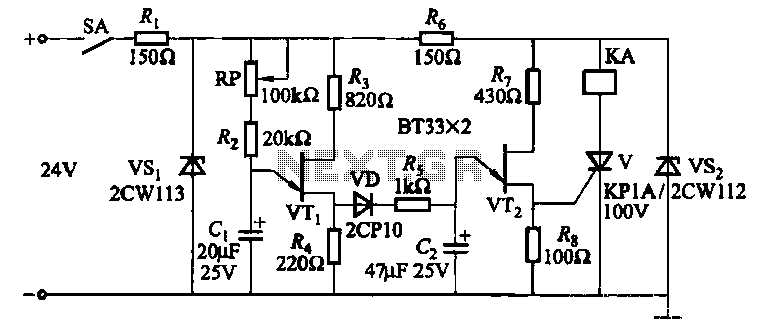
This circuit consists of three single-junction transistor time relay circuits utilizing a pulse charging mechanism, allowing for extended delay times of up to several minutes. The first stage delay circuit incorporates unijunction transistors (VTi) and other components, where capacitor...
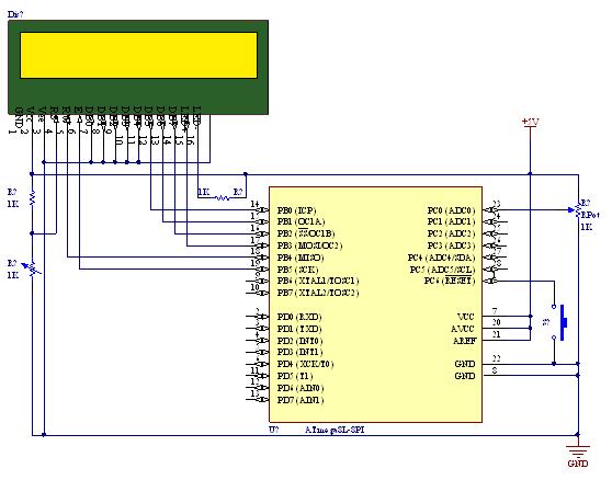
A straightforward tutorial on utilizing the ADC (Analog to Digital Converter) unit of the AVR microcontroller, demonstrated with the Atmega8, including a circuit diagram and code examples. The ADC unit in the Atmega8 microcontroller is a crucial component that allows...
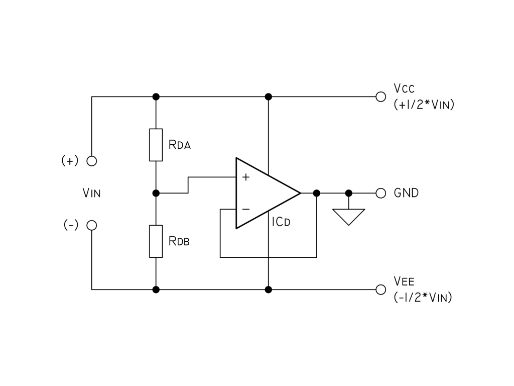
To eliminate noise, a 100µF capacitor and a 100nF bypass capacitor are used across the supply, along with two 10nF capacitors in parallel with the resistors Rda and Rdb (each 10K). For current limiting, a 22K resistor is paralleled...