
555 timer IC as A-stable Multivibrator

The astable multivibrator configuration of the 555 timer IC operates continuously in a square wave output mode, making it suitable for generating clock pulses or timing applications. In this setup, the timer does not have a stable state; it oscillates between high and low states by charging and discharging the timing capacitor (C1) through the resistors (R1 and R2).
The circuit operates as follows: When power is applied, the capacitor C1 begins to charge through resistors R1 and R2. The voltage across C1 rises until it reaches the threshold voltage (2/3 Vcc), at which point the output at Pin 3 switches from high to low. This transition causes C1 to discharge through R2 until the voltage drops to the trigger level (1/3 Vcc), at which point the output switches back to high, and the cycle repeats.
The frequency of oscillation (f) and the duty cycle (D) of the output waveform can be calculated using the following formulas:
1. Frequency (f) = 1.44 / ((R1 + 2R2) * C1)
2. Duty Cycle (D) = (R2 / (R1 + 2R2)) * 100%
These equations indicate that by adjusting the values of R1, R2, and C1, the frequency and duty cycle of the output waveform can be precisely controlled, allowing for versatile applications in timers, pulse-width modulation, and tone generation circuits.
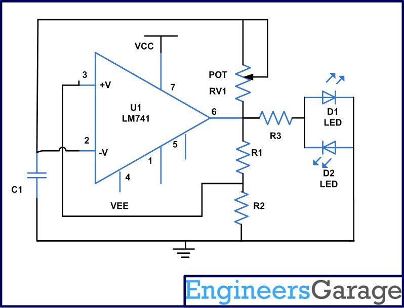
In practical applications, the 555 timer IC is widely used in various electronic devices, including LED flashers, tone generators, and frequency modulators, due to its reliability and ease of use. Proper selection of the timing components is crucial for achieving the desired performance in specific applications.A 555 timer IC is used a a-stable multivibrator as shown in the given figure (A). The threshold input is now connected to the trigger input (Pin 2), the resister R1, R2 and capacitor C1 for timing network which set the frequency of the oscillator.. 🔗 External reference
Related Circuits
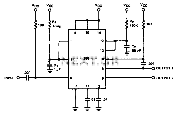
The circuit consists of four 2-input NAND gates and a CMOS CD4011 type 555 timer, allowing for either a static or high-time period output while maintaining minimal power consumption. Additionally, the circuit features a 3-door and 4-door composition RS...
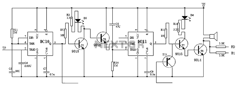
Child lock voltage comparator 555 monostable circuit, a counter, JK flip-flop, UPS power supply design digital logic circuit, electronic door control, and various additional circuitry to ensure the safety circuit can operate with a high safety factor. The circuit...
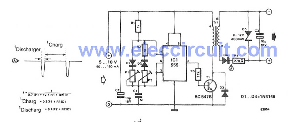
This circuit is a simple DC to DC converter designed for digital circuits. It operates with a supply voltage of 5V and provides an output voltage that steps up to a maximum of 10V-12V DC. The circuit utilizes an...

The FM modulator circuit is a straightforward FM modulation design utilizing the IC 555, where the resulting modulated signal is dependent on the frequency of the input signal. The output signal is stable and of good quality, eliminating the...
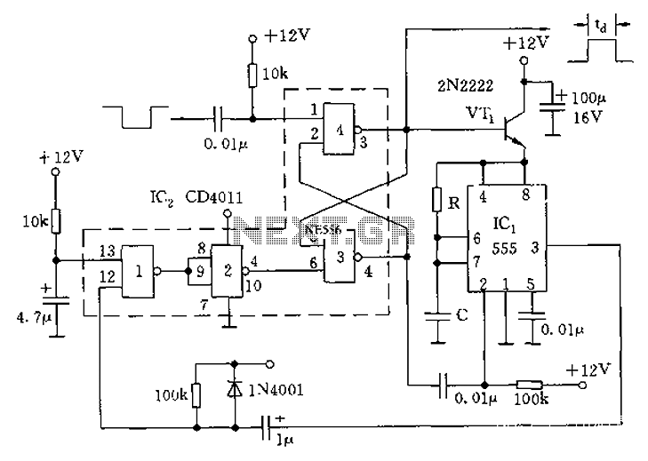
By utilizing both halves of a dual timer, sequential timing can be achieved. The output of the first half is connected to the input of the second half through a 0.1 µF coupling capacitor. The delay time ti is...
An astable multivibrator is an electronic device that continuously alternates between two states in its output. When one state is high, the other is low. This characteristic is useful for generating a continuous stream of pulses without the need...