
Sequential timer

The described circuit employs a dual timer, typically a 555 timer IC, to create a sequential timing mechanism. The first half of the timer operates in monostable mode, generating a time delay ti based on the values of resistor R1 and capacitor C1. When the circuit is powered, a momentary connection of pin 6 to ground triggers the timer, causing it to output a high signal for a duration defined by the time constant τ1 = R1 × C1.
The output from the first half is then fed into the second half of the timer through a 0.1 µF coupling capacitor. This capacitor serves to block any DC offset while allowing the timing pulse to pass through, effectively triggering the second half of the timer. The second half operates similarly in monostable mode, with its timing determined by resistor R2 and capacitor C2, resulting in a delay ta.
This configuration allows for a precise control of timing sequences in various applications, such as in flashing LEDs, pulse generation, or timed events in control systems. The selection of R1, C1, R2, and C2 values will define the specific timing intervals, enabling customization for different operational requirements. The circuit can be further enhanced by adding additional components such as diodes for protection, or transistors for driving higher loads, depending on the intended application.By utilizing both halves of a dual timer it is possible to obtain sequential timing. By connecting the output of the first half to the input of the second half via a 01 µF coupling capacitor sequential timing may be obtained. Delay ti is determined by the first half and ta by the second half delay. The first half of the timer is started by momentarily connecting pin 6 to ground When it is turned out (determined by 1R1C1), the second half begins. Its duration is determined by 1R2C2.
Related Circuits
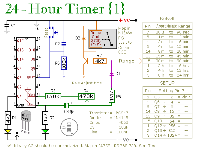
A pair of multi-range timers capable of timing periods up to 24 hours and beyond. Both versions are fundamentally similar, with the primary distinction being that Version 1 energizes the relay when the time expires, while Version 2 de-energizes...
The 555 timer integrates both analog and digital functions within a scaled integrated device. Typically manufactured using a bipolar process, it is designated as the 555 timer, while the CMOS version is referred to as the 7555. In addition...
This tutorial on the PIC16F877 microcontroller addresses the question of how to utilize Timer0 and manage its interrupts. It utilizes the PIC16 simulator for demonstration purposes. The PIC16F877 microcontroller is a versatile device widely used in embedded systems. Timer0 is...
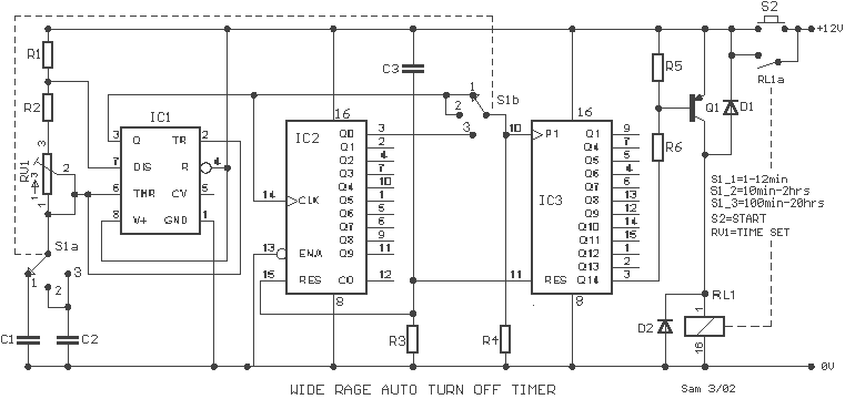
A wide range auto turn OFF timer covering 1 minute to 20 hours in three ranges with S1. As soon as power is applied to the circuit, the IC1 [555] starts to oscillate and feeds clock pulses to the...
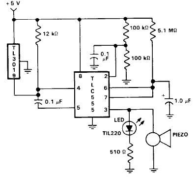
This door open alarm electronic project is designed using a linear hall effect device and a 555 timer circuit. The project utilizes the TL3103 linear hall effect device for detecting the angle of rotation. The TL3103 is positioned within...
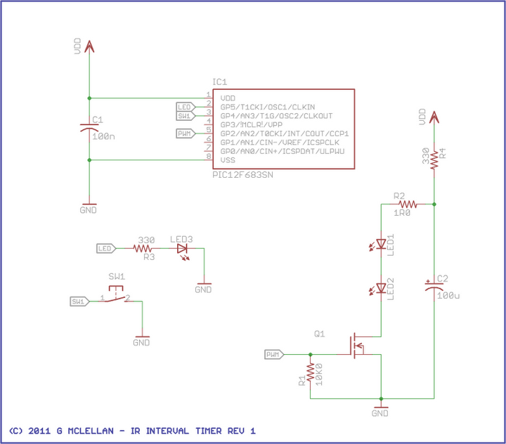
This project aims to build an infrared (IR) interval timer that can be utilized to capture images, such as time-lapse movies of sunrises and night skies. The IR interval timer circuit is designed to automate the process of taking...