
555 Astable oscillator

This circuit functions by generating a continuous square wave output, where the timing capacitor C is charged and discharged in a cycle determined by the external current sink. The duty cycle of the output is inherently low due to the nature of the timing mechanism. The external current sink plays a crucial role in controlling the discharge rate of the capacitor, which in turn influences the pulse duration and frequency of the output signal.
In operation, when the timing capacitor C charges, it reaches a threshold voltage that triggers the output to go high. During this period, the voltage V across the capacitor rises exponentially. Once the external current sink is activated, it discharges the capacitor, causing the voltage to drop rapidly, resulting in a negative-going ramp. The timing of this cycle can be adjusted by changing the values of the capacitor and the resistive components associated with the current sink.
The design of this multivibrator is particularly useful in applications where precise timing intervals are critical, such as in clock generation for digital circuits or in timing applications where low duty cycles are acceptable. The ability to achieve a wide range of pulse durations by manipulating the external components allows for versatility in various electronic applications.This free-running multivibrator uses an external current sink to discharge the timing capacitor, C. Therefore, interval ^ may easily be 1000 the pulse duration, t1( which defines a positive output. Capacitor voltage, V^, is a negative going ramp with exponential rise during the pulse output periods. This as is has low duty cycle.
Related Circuits
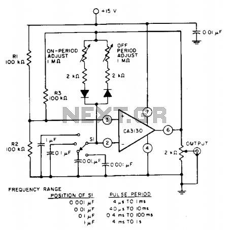
The pulse repetition rate is determined by adjusting switch SI to the desired position, and this rate remains relatively constant even when the resistors that control the on-period and off-period are modified. Resistors R1 and R2 set the biasing...
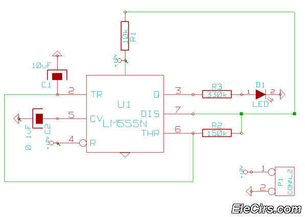
This is a very simple 555 timer circuit that serves as a straightforward theft deterrent, which may be just as effective. The idea is to have a flashing red LED indicate that your car is protected. This device can...
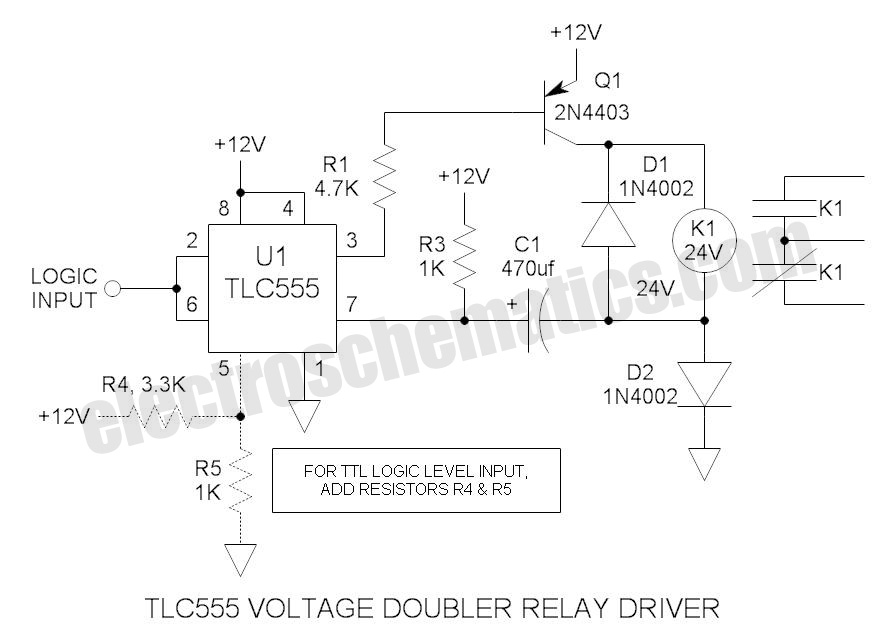
These novel relay driver circuits can activate a relay with a coil voltage rating that is double the Vcc. After activation, the relay armature is held in place. The relay driver circuits described are designed for applications requiring the control...
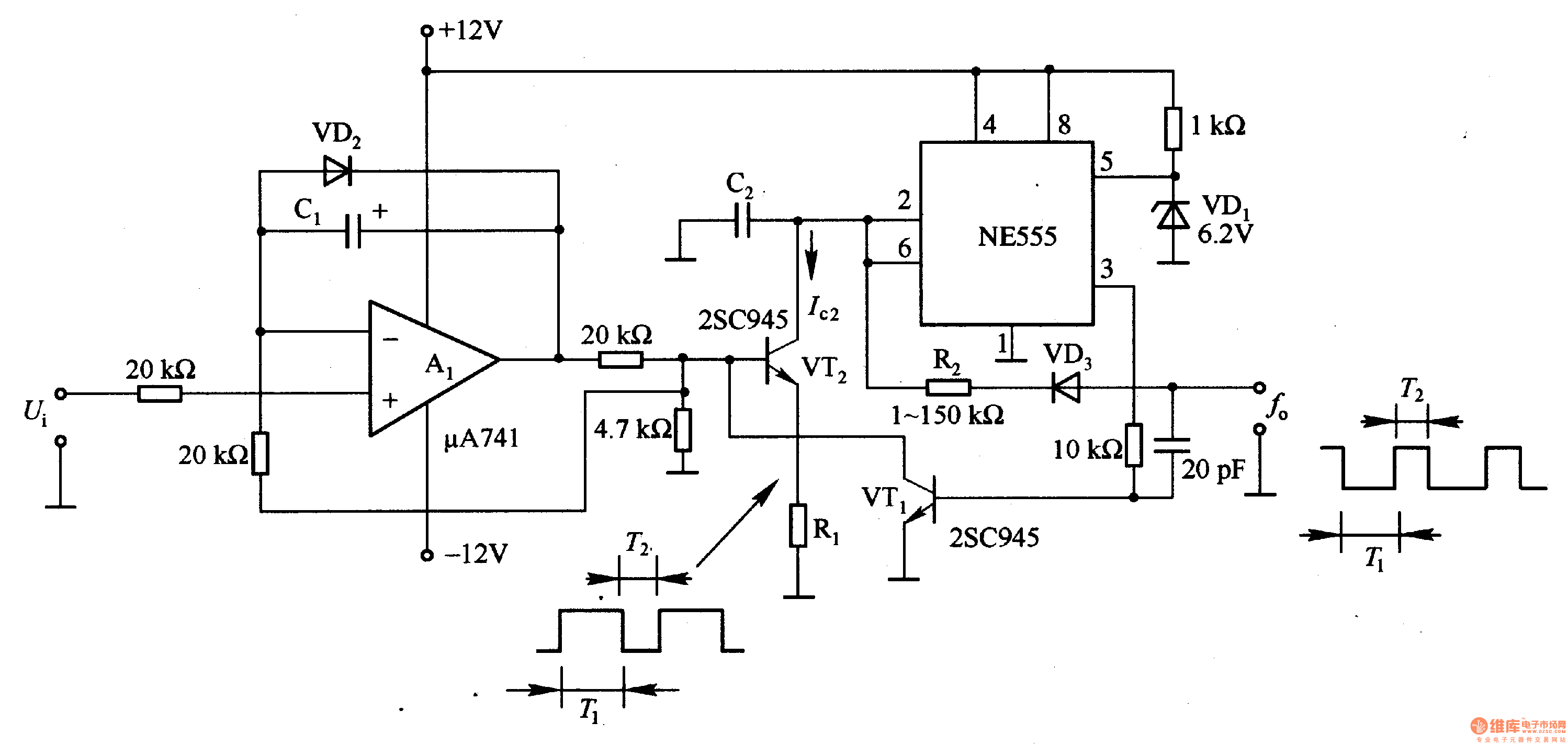
In the circuit, the oscillation frequency of the NE555 is controlled by VT2. When the output at pin 3 is low (during the T1 period), VT1 stops conducting, and VT2 begins to conduct with a current Ic2 flowing through...
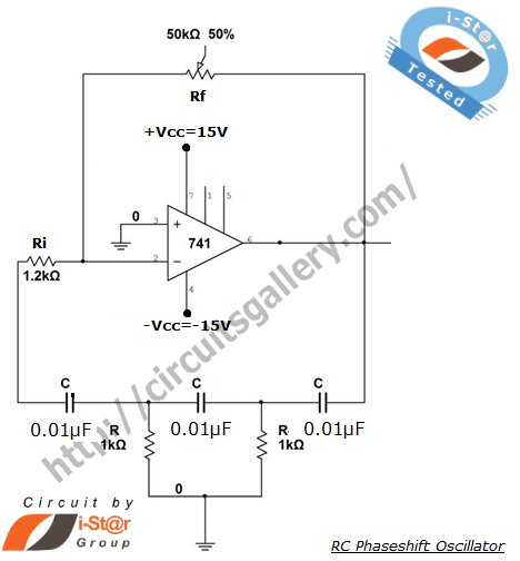
A phase-shifted oscillator can be constructed using a basic operational amplifier (op-amp), three resistors, and three capacitors. One of the resistors should be adjustable, while the other components should have the same value. This oscillator design exhibits low distortion...
The circuit presented is a standard Colpitts oscillator, commonly utilized in many amateur radio homebrew transmitters. This specific circuit is designed to operate effectively within a frequency range of 1500 kHz to 8000 kHz. To accommodate lower frequencies, it...