
Application Circuit CW4960 CW4962 dual voltage + 5V 1.5A -12V 100mA output

The circuit design features two primary voltage outputs: +5V and -12V, achieved through the integration of the CW4962 and CW4960 voltage regulators. The +5V output is designed to supply a maximum current of 1.5A, making it suitable for powering various electronic devices that require stable voltage and current levels. The regulator ensures that voltage fluctuations are minimized, providing a reliable power source for sensitive electronics.
For the -12V output, the circuit employs a transformer to step down the input AC voltage. The secondary winding of the transformer is configured to produce the necessary -12V output. This AC voltage is then rectified using a diode bridge, which converts the AC signal into a pulsating DC signal. Following rectification, a filter capacitor is used to smooth out the rectified output, reducing ripple voltage and ensuring a stable -12V DC output.
The choice of using a transformer instead of an inductor is significant in this design. Transformers are capable of providing isolation between the input and output, enhancing safety and reducing noise in the power supply. Additionally, the transformer allows for efficient voltage transformation, making it a suitable choice for this application.
Overall, this stabilized power supply circuit is designed to meet the demands of various electronic applications, providing reliable and consistent voltage outputs while ensuring protection and efficiency through its component selection and design architecture. By the CW4962, CW4960 constituted + 5V/1.5A, -l2V/100mA stabilized power supply circuit is shown. Wherein, + 5V, 1.5A is the main power supply. Output circuit using the transfo rmer instead of inductor. -12V, L00mA auxiliary power transformer secondary winding is rectified and then, get filtered.
Related Circuits
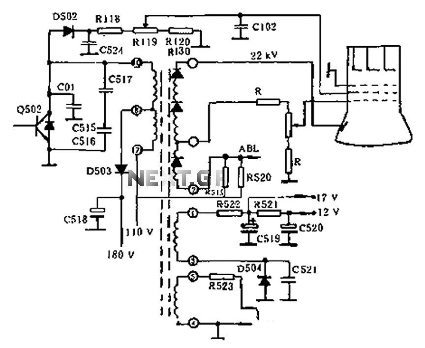
The circuit diagram of the Swallow CS37-2 type color TV illustrates the feeding tube configuration. The filament voltage is supplied by the line flyback transformer, with a current-limiting resistor R523. The accelerating voltage is managed by D502, which rectifies...
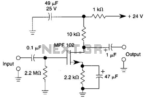
This JFET preamplifier has a gain of approximately 20 dB and a bandwidth exceeding 100 kHz. It is useful as a low-level audio amplifier for high-impedance sources. The described JFET (Junction Field Effect Transistor) preamplifier is designed to amplify low-level...
This project involves outdoor LED solar garden lights, which function as an automatic garden lighting system utilizing a light-dependent resistor (LDR) and a 6V/5W solar panel. During daylight hours, the internal rechargeable 6 Volt sealed lead-acid (SLA) battery is...

This circuit is used to select modes of operation. The accelerometer is utilized to generally move the snake arm, while the Hall effect sensors are designed to enable various functions. The circuit described incorporates an accelerometer and Hall effect sensors...
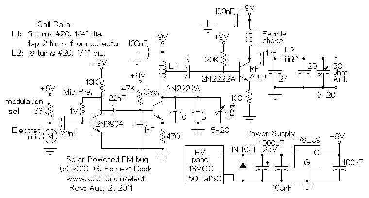
Here are some utility circuits for use with the Ramsey FM10a, and other small FM stereo transmitter kits. This information may be helpful for setting up a micro powered FM radio station. The FM10a and similar kits tend to...
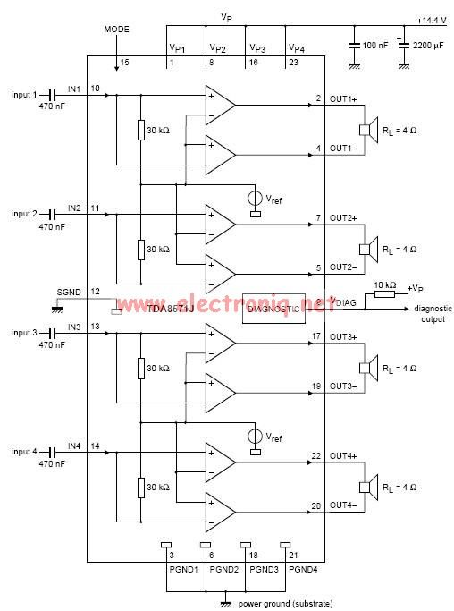
This electronic circuit diagram represents an audio power amplifier utilizing the TDA8571J integrated circuit. It is a class-B output amplifier configured in a BTL (Bridge-Tied Load) arrangement, featuring four amplifiers, each with a gain of 34 dB. The main...