
555 timer IC Inverter circuit schematic 12V to 220V

The inverter circuit described operates on the principle of converting direct current (DC) from a 12V source into alternating current (AC) at a voltage level of 220V. The core component, the 555 timer IC, is configured in astable mode, which generates a continuous square wave output. This output is essential for creating the necessary AC waveform.
In the circuit, the 555 timer's output is connected to the base of the transistor 2N5192, which acts as a switch. When the 555 timer outputs a high signal, the transistor conducts, allowing current to flow from the 12V battery through the primary winding of the transformer. The transformer is crucial as it steps up the voltage from 12V to 220V, suitable for typical household electrical devices.
The transistor 2SC4029 plays a role in managing the oscillations produced by the 555 timer and ensuring that the signal is appropriately amplified before reaching the transformer. This transistor is selected for its capability to handle the power levels involved in the circuit.
The output frequency of the inverter is set at approximately 50 Hz, which is standard for AC power in many regions. This frequency is determined by the timing components connected to the 555 timer, specifically the resistors and capacitors that set the charging and discharging times.
Overall, the described inverter circuit is a practical solution for converting low-voltage DC power into high-voltage AC power, making it suitable for applications where backup power is necessary. The inclusion of a battery charger circuit ensures that the 12V battery remains charged and ready for use when needed. This simple yet effective design can be implemented with readily available components, making it accessible for hobbyists and those interested in electronics.This article explains What is inverter And how can you construct your own simple low cost 12V to 220V inverter circuit. An inverter is nothing but a DC to AC converter. Inverters are very useful electronics products for compensating emergency power failure, as it performs DC to AC conversion.
Here is the simple inverter circuit diagram using 555 timer IC. The astable multivibrator mode operation of 555 timer utilized here for AC oscillations and these oscillations are switched via transistor 2SC4029 to a transformer. The transformer step ups the voltage to 220V AC. Use a 12V battery and Battery charger circuit for this project. Design of inverter circuit is also given. The output pulse from the 555 astable multivibrator is fed to the base of power transistor 2N5192. The 2N5192 transistor works as a switch, so the 12V DC supply passed through the transformer at a rate of 50 times per second.
🔗 External reference
Related Circuits
The alarm detector circuit operates differently from the Ultrasonic Alarm (1). In Ultrasonic Alarm (1), an alarm output is triggered by the detection of a reflected wave from an object during the setup time. Conversely, in this circuit, an...
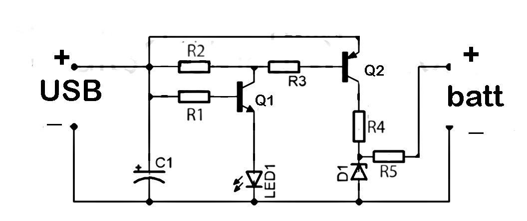
This document discusses the series used in USB connections for charging batteries. The output voltage ranges from 4.7 volts to 5 volts DC, which is suitable for charging mobile phones and other battery types. The circuit described enhances the...
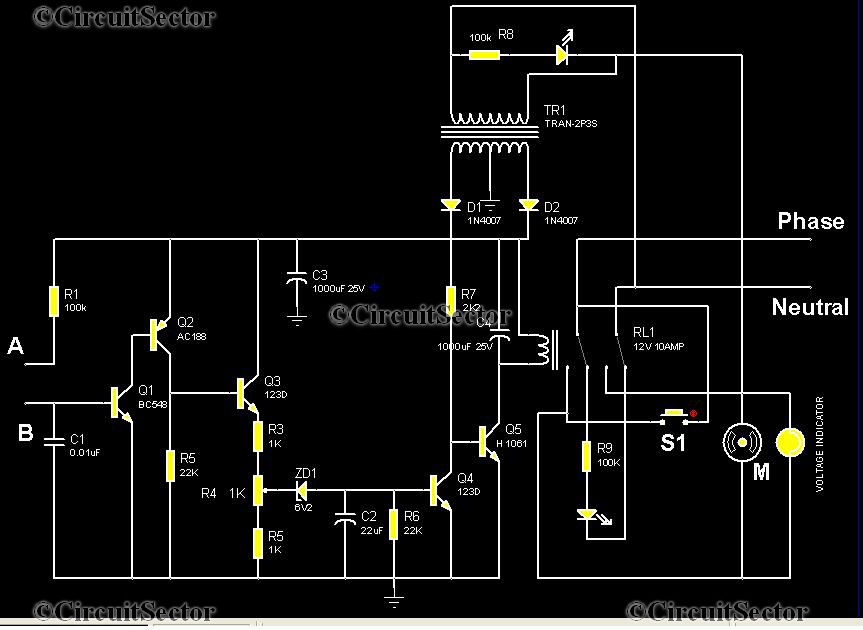
This is an automatic water tank controller designed to manage the operation of a water pump using a 12V 10A relay. When the water level in the tank creates a short circuit between points A and B in the...
A fluorescent tube is connected in an LC resonant circuit consisting of inductor L2 and capacitor C9. The bidirectional breakdown diode VD4 initiates the starting circuit. When AC power is applied, the gate potential of transistor VT2 increases due...
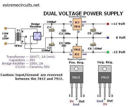
The following circuit diagram of a dual voltage power supply can be used for miscellaneous applications. It requires a few components to build. The most important components of this circuit are regulators: 1: (AN) 7812 and 2: (AN) 7912....
As mentioned in the chapter about the DAC, this circuit shifts the voltage output range. The following diagram explains its operation and structure. The circuit's outputs are connected to the input pins of the power operational amplifiers. The described circuit...