
555 timer led flasher circuit

The LED flasher circuit employs the 555 timer in astable mode, allowing it to produce a continuous square wave output. This configuration is ideal for generating the flashing effect of the LEDs. The frequency of the flashing can be adjusted by varying the values of two resistors and a capacitor connected to the timer.
Typically, two resistors (R1 and R2) and one capacitor (C1) are used to set the timing intervals. The relationship between these components determines the rate at which the LEDs will flash. The output from the 555 timer is connected to a transistor, which acts as a switch to control the current flowing through the LEDs. This configuration ensures that the LEDs receive sufficient current to illuminate brightly while also allowing for efficient power management.
In addition to the basic components, a diode may be included in the circuit to prevent reverse polarity, ensuring the longevity of the timer and LEDs. The circuit can be powered by a standard DC voltage source, commonly ranging from 5V to 15V, depending on the specifications of the components used.
This design can be implemented in various applications, such as decorative lighting, warning signals, or any scenario where a flashing LED indication is required. The simplicity of the circuit makes it an excellent choice for beginners in electronics, as well as for more experienced engineers looking for a quick solution for LED flashing applications.This LED Flasher circuit is based on the 555 timer IC. The LED Flasher circuit diagram is very simple and require few external components. When the circuit is working the red LEDs will flash at a set frequency one by one like at the railway crossing indicator. 🔗 External reference
Related Circuits

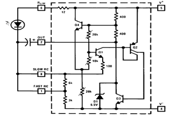
These accessories are low-cost, high-speed, bifet-input operational amplifiers utilizing internally compensated voltage (BI-FET II technology). They require low supply voltages while offering a wide gain bandwidth product and fast slew rate. Additionally, well-matched high voltage JFET input devices accommodate...
An H-bridge is a type of circuit utilized for controlling the direction (and occasionally the speed) of an electric motor by employing a single polarity voltage. The circuit functions by reversing the current flow to change the motor's rotation...

The mechanics of the Quantized Random Voltage function are intriguing. Instead of having fixed quantization steps for each output of the 4006 shift register, it is proposed to make the voltages adjustable through potentiometers. The Quantized Random Voltage function...
Variable-gain amplifiers (VGAs) can be used in many types of systems, such as radio receivers. In this system, the input signal voltage depends on an. Variable-gain amplifiers (VGAs) are integral components in various electronic systems, particularly in radio receivers where...
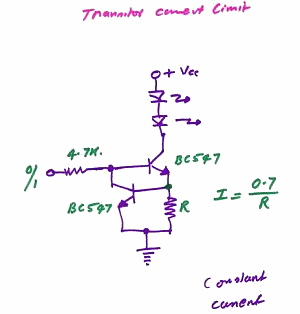
This is a constant current source LED driver. When the upper NPN transistor is activated by a voltage through a 4.7kΩ resistor, the LED lights up. It is assumed that the lower NPN transistor is absent. The current flowing...
The schematic diagram below illustrates a typical 1.5V flasher circuit using the LM3909. The LM3909 is a monolithic oscillator designed specifically for flashing Light Emitting Diodes (LEDs). The LM3909 flasher circuit operates at a low voltage of 1.5V, making it...