
Digitally Controlled High Frequency VGA

Variable-gain amplifiers (VGAs) are integral components in various electronic systems, particularly in radio receivers where they play a critical role in managing signal levels. VGAs are designed to adjust the gain of an input signal dynamically, allowing for optimal signal processing under varying conditions. This adaptability is essential in applications where the amplitude of incoming signals can fluctuate significantly, ensuring that the output remains within the desired range for further processing.
In a typical radio receiver system, the VGA is positioned after the antenna and front-end filter stages. The input signal, which may vary in strength due to distance from the transmission source or interference, is fed into the VGA. The gain of the amplifier can be controlled either manually or automatically, depending on the design of the receiver. Automatic gain control (AGC) circuits are often employed to adjust the gain in real-time, ensuring consistent output levels regardless of input variations.
The VGA can be implemented using various technologies, including analog and digital methods. Analog VGAs utilize variable resistors or transistors to change gain, while digital VGAs may use digital potentiometers or programmable gain amplifiers controlled by microcontrollers. The choice of technology impacts the performance characteristics, such as linearity, bandwidth, and noise figure, which are critical in maintaining signal integrity.
Careful consideration must be given to the design parameters of the VGA, including input and output impedance, frequency response, and distortion characteristics. These factors influence the overall performance of the radio receiver, affecting sensitivity, selectivity, and signal-to-noise ratio. By optimizing these parameters, VGAs can significantly enhance the performance of communication systems, enabling clearer and more reliable signal reception.Variable-gain amplifiers (VGAs) can be used in may types of systems, such as radio receivers. In this system, the input signal voltage depends on an. 🔗 External reference
Related Circuits
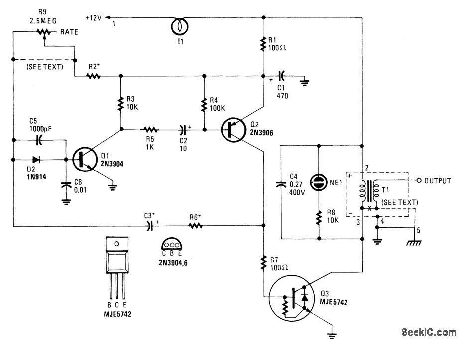
This high-voltage pulse supply generates pulses up to 30 kV. Transistors Q1 and Q2 create a multivibrator in conjunction with peripheral components R1 through R6 and capacitors C1, C2, C3, C5, C6, and diode D2. Resistor R9 adjusts the...
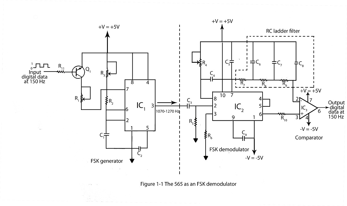
The frequency shifting keying technique is utilized to transmit binary data. The circuit diagram includes a description of an FSK demodulator that employs the 565 integrated circuit for frequency shift keying. The frequency shift keying (FSK) technique is a form...
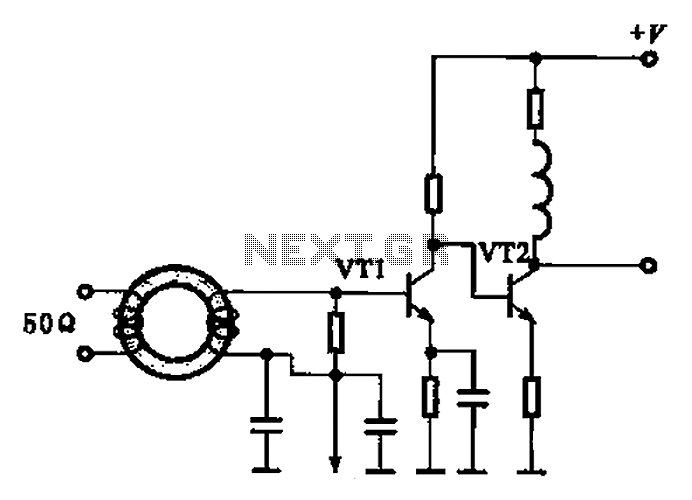
A broadband high-frequency amplifying circuit is primarily composed of a high-frequency matching transformer and an amplifying transistor. This circuit is designed to handle large high-frequency signals. The input of the amplifier circuit utilizes a matching transformer to ensure that...
This simple, one-transistor amplifier provides a voltage gain of over 1000 (60 dB) for an active aerial impedance crystal earphone. The gain is achieved by replacing the standard load resistor with a constant-current diode that supplies 1/2 mA while...

When discussing fan control, there are generally two methods: linear control and pulse-width modulation (PWM) control. Linear control is the most commonly used method, which involves reducing the voltage supplied to the fan. For a fan rated at 12...
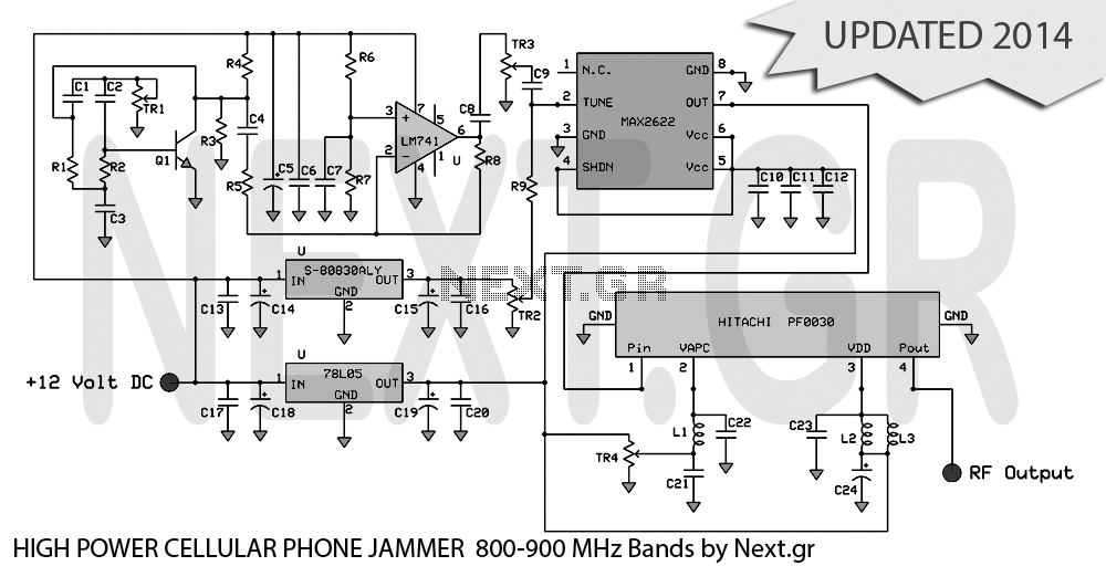
UPDATED 2014 This project presents the original high-power mobile phone jammer circuit, with all updates posted here. Caution is advised regarding the use of this device, as it is illegal. The purpose of sharing this circuit is solely for...