
LM3909 Typical 1.5V Flasher Schematic Diagram and Datasheet

The LM3909 flasher circuit operates at a low voltage of 1.5V, making it suitable for battery-powered applications. It is capable of driving one or more LEDs, providing a visual indication through periodic flashing. The circuit utilizes the internal oscillator of the LM3909, which generates a square wave output that controls the flashing rate of the connected LEDs.
Key components of the circuit include the LM3909 integrated circuit, resistors, capacitors, and the LED itself. The resistor values and capacitor size can be adjusted to modify the flashing frequency and duty cycle of the output. Typically, a larger capacitor will result in a slower flashing rate, while a smaller capacitor will increase the flashing speed.
The circuit configuration involves connecting the LED in series with a current-limiting resistor to prevent excessive current flow, which could damage the LED. The output pin of the LM3909 is connected to the anode of the LED, while the cathode is grounded. The timing components, namely the resistor and capacitor, are connected to the timing pins of the LM3909, allowing for precise control over the flashing characteristics.
This flasher circuit is widely used in various applications, including decorative lighting, indicators, and visual alerts, due to its simplicity and efficiency. The LM3909's low power consumption makes it an ideal choice for projects requiring prolonged battery life.The schematic diagram below appears LM3909 Typical 1.5V Flasher circuit. It is known that LM3909 is an oscillator, a monolithic one, which is designed to flash Light Emitting Diodes (LED) 🔗 External reference
Related Circuits
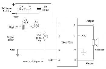
This is an audio amplifier circuit that uses the TDA7052 as the main component, along with five additional components to support its operation. The ideal supply voltage for this circuit is approximately 6-12V, and it does not require a...

The CA3140 is a 4.5 MHz BiMOS operational amplifier featuring MOSFET inputs and a bipolar output. This operational amplifier integrates the benefits of PMOS transistors and high voltage performance. The CA3140 operational amplifier is designed to provide high-speed performance while...
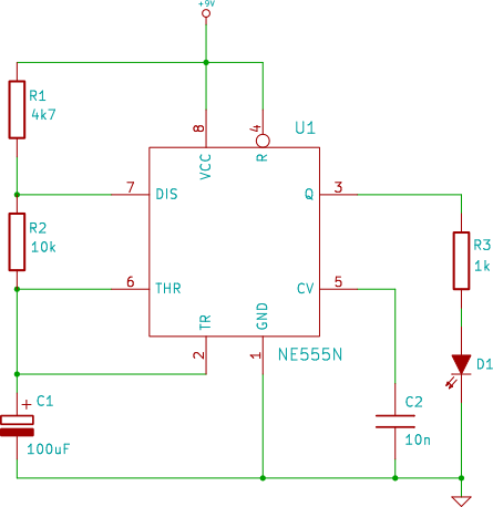
The connection point for the positive terminal of the 9V battery is represented as a circle at the end of a line labeled "+9V." This indicates where to apply power to the circuit. The 0V or "GND" of the...

It can be assumed that most 555 timer chips from various manufacturers are interchangeable due to their similar pin configurations. However, the programs or diagrams may simplify the pin arrangements, leading to potential confusion. Custom routing may be necessary...
The metal detector circuit consists of several key components including the probe oscillator, reference oscillator, oscillation signal processor, mixing amplifier, and ammeter PA. The probe oscillator is made up of the oscillating tube VI, exploration coil L1, capacitors C1...
The 555 timer on the right is configured as an alarm sound generator, while the second 555 timer on the left functions as a 1 Hz astable multivibrator. The output from the left timer modulates the frequency of the...