
555 timer Mono stable (one shot) circuit circuit
")
The described circuits utilize the 555 timer in monostable mode, where the timer generates a single output pulse in response to a trigger input. In the first circuit, the push button serves as the trigger, initiating the timing cycle upon being pressed. The timing duration is determined by the resistor-capacitor (RC) network connected to the 555 timer. When the button is pressed, the capacitor begins charging through the resistor, and once the voltage across the capacitor reaches two-thirds of the supply voltage, the output of the timer switches from low to high, activating the relay.
In the second circuit, designed for shorter timing applications, the capacitor is connected in parallel with the push button. This arrangement allows the capacitor to charge quickly when the button is pressed, but it also isolates the timer from the continuous closure of the switch. As a result, the timer only registers the initial transition of the switch from open to closed, effectively ignoring any subsequent state changes while the switch remains closed. This feature is particularly useful in applications where the user might hold down the button for an extended period, as it prevents unintended relay activation beyond the desired timing duration.
Both circuits can be powered by a standard DC power supply compatible with the 555 timer's operating voltage range, typically between 4.5V and 15V. The relay used in conjunction with the timer can be selected based on the load requirements, ensuring it can handle the current and voltage specifications of the intended application. The output of the 555 timer can be connected directly to the relay's coil, with appropriate flyback diode protection to prevent voltage spikes from damaging the timer when the relay is de-energized.
Overall, these circuits provide flexible solutions for controlling relay operations based on user input, with the capability to adjust timing characteristics through the selection of resistor and capacitor values in the timing network.The two circuits illustrate using the 555 timer to close a relay for a predetermined amount of time by pressing a momentary N/O push button. The circuit on the left can be used for long time periods where the push button can be pressed and released before the end of the timing period.
For shorter periods, a capacitor can be used to isolate the switch so that only the initial switch closure is seen by the timer input and the switch can remain closed for an unlimited period without effecting the output.. 🔗 External reference
Related Circuits
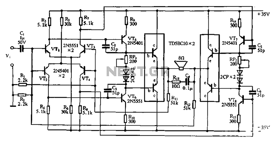
The bridge is a low-frequency push-pull power amplifier circuit with a simple structure, capable of delivering an output power of up to 1W. It can be utilized as an external amplifier for devices such as Walkmans, phones, doorbells, alarms,...
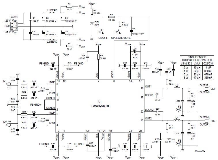
This high-power Class D audio amplifier electronic project utilizes the TDA8920BTH audio power amplifier integrated circuit (IC). This power amplifier IC is characterized by its high efficiency and low heat dissipation, delivering significant output power. The typical output power...
A Butterworth filter is a type of filter characterized by a frequency response that is flat within the passband region. This filter was first described by British engineer Stephen Butterworth. A Butterworth filter is designed to provide a maximally flat...
Constantly changing light and sound analog controller circuit 01 The described circuit functions as an analog controller designed to modulate light and sound outputs in a dynamic manner. This circuit typically integrates various electronic components, including resistors, capacitors, transistors, and...
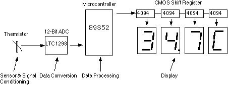
This assignment pertains to the course "Designing Microprocessor Based Instrumentation." The project features a board that utilizes a 12-bit ADC, a C program with digital filtering, and an LED display interface. It achieves a temperature reading sensitivity of 0.1°C....

Digital Command Control (DCC) provides significant advantages over traditional DC analog control systems, primarily due to its simplified wiring. DCC enables the individual control of multiple locomotives on the layout without requiring electrical isolation of track sections. The main...