
First-order butterworth active Low-pass filter circuit

A Butterworth filter is designed to provide a maximally flat frequency response in the passband, ensuring minimal signal distortion. The filter's roll-off rate is moderate, providing a smooth transition between the passband and the stopband. The order of the Butterworth filter determines the steepness of the roll-off; higher-order filters exhibit a sharper transition but may introduce more phase distortion.
In practical applications, Butterworth filters are employed in various electronic circuits, including audio processing, communication systems, and signal conditioning. They can be realized using passive components such as resistors, capacitors, and inductors, or through active components like operational amplifiers. The most common configurations include low-pass, high-pass, band-pass, and band-stop filters.
The design of a Butterworth filter involves selecting the desired cutoff frequency and filter order based on the application requirements. The transfer function of an nth-order Butterworth filter can be expressed in terms of its poles, which are evenly spaced around a semicircle in the left half of the complex plane. This characteristic contributes to the filter's smooth frequency response.
When implementing a Butterworth filter in a circuit, careful consideration must be given to component tolerances and temperature stability to ensure the filter performs as intended across varying conditions. The filter's performance can be simulated using software tools to analyze its frequency response, phase response, and transient behavior before physical implementation.Butterworth filter is a filter whose freq response is flat over the passband region. British engineer Stephen Butterworth first described this 🔗 External reference
Related Circuits
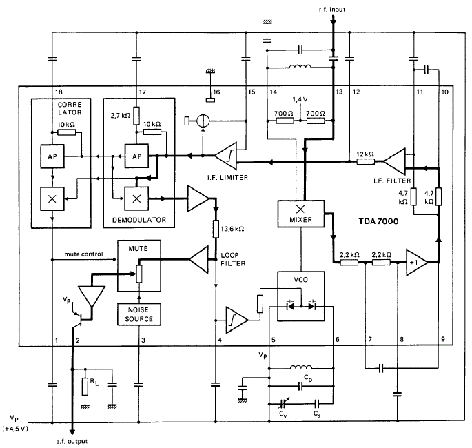
GENERAL DESCRIPTION The TDA7000 is a monolithic integrated circuit designed for mono FM portable radios or receivers, emphasizing minimal peripheral components to achieve compact dimensions and reduced costs. This integrated circuit features a Frequency-Locked-Loop (FLL) system with an intermediate...
This sound wattmeter utilizes a series of colored LEDs as a scale to display the relative power output of an amplifier in watts. It is designed for easy integration into a speaker box, requiring only a connection to a...
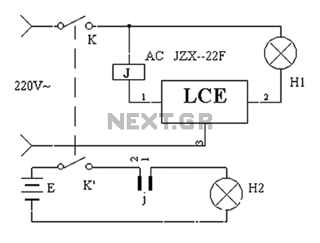
The application circuit operates the device as illustrated below, allowing for intermittent lighting in specific situations (e.g., during surgery). It utilizes an LCE module for blackout emergency lighting, which activates automatically after a power failure, ensuring uninterrupted illumination. In...

This circuit is designed as a 10-channel LED sequencer with the addition of solid-state relays for controlling AC lamps. The circuit operates using relays. The relay depicted in the diagram is a Radio Shack 3 amp unit (part no....
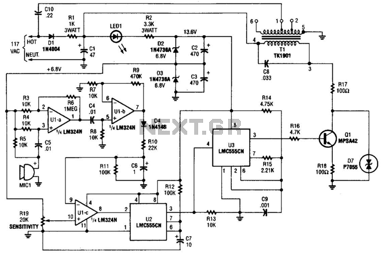
The baby-alert transmitter is constructed using an LM324 quad operational amplifier (U1), two LMC555CM CMOS oscillator/timers (U2 and U3), along with several supporting components. The transmitter activates upon detecting sound at MIC1, emitting a signal. Its operational frequency is...
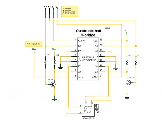
A stepper motor controller based on schematics available on the Arduino website. Initially, a two-pin configuration was attempted for a bipolar stepper motor, but it did not function as expected, especially with the library provided on the site. The...