
555 Touch-sensitive switch circuit diagram
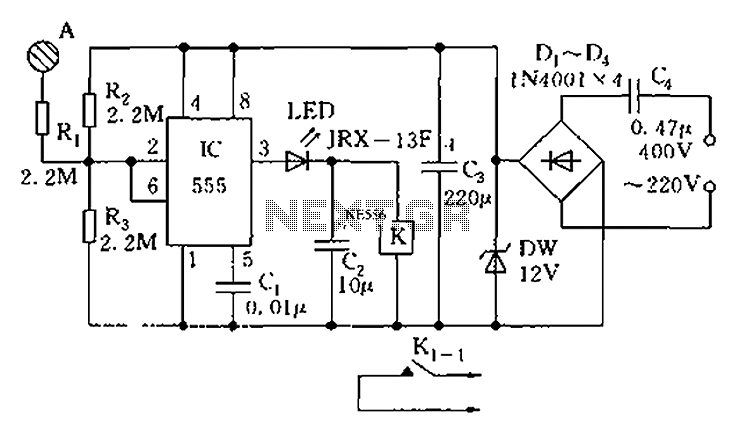
The touch sensor switch circuit operates on the principle of capacitive sensing, where the presence of a hand near the metal sheet alters the capacitance, triggering the circuit's response. The step-down rectifier circuit is responsible for converting the AC voltage to a lower DC voltage suitable for the operation of the 555 timer and other components. The 555 timer, configured in a monostable or astable mode, serves as the core of the timing mechanism, generating a pulse when activated.
Upon the initial touch of the hand to the metal sheet A, the capacitance change is detected, sending a signal to the internal comparator within the 555 timer. This comparator assesses the voltage levels and, upon detecting the touch, sets the output state to K. This action energizes the relay or switch associated with contact K1-1, effectively closing the circuit and allowing current to flow to the connected load.
If the hand remains in contact with the metal sheet, the circuit remains in this activated state. However, if a second trigger occurs—such as the removal of the hand or a subsequent touch—the circuit resets, and the output at K is released, opening contact K1-1 and disconnecting the load. This functionality allows for a simple yet effective method of controlling devices with a non-mechanical touch interface, enhancing user interaction without the need for physical switches.
The inclusion of flip-flops in the circuit design adds a layer of stability and control, enabling the circuit to maintain its state until a defined condition is met, preventing accidental activation or deactivation. Proper component selection, including capacitors and resistors, is crucial for ensuring the sensitivity and responsiveness of the touch sensor switch circuit. As shown in FIG touch sensor switch circuit diagram The circuit consists of step-down rectifier circuit 555 and flip-flops. When the hand touches the metal sheet A, sensor sign al causes the internal comparator flip 555 is set, K pull, contact K1-1 closed; if more trigger at A, then K release, K1-1 disconnected.
Related Circuits
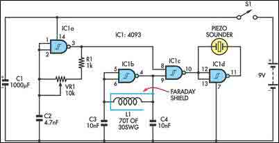
The circuit incorporates two oscillators, both operating at about 40kHz. The first, IC1a, is a standard CMOS oscillator with its frequency adjustable via VR1. The frequency of the second, IC1b, is highly dependent on the inductance of coil L1,...
NOTE: There is no guarantee as to the suitability of said circuits and information for any purpose whatsoever other than as a self-training aid. I.E. If it blows your equipments, trashes your hard disc, wipes your backup, burns your...
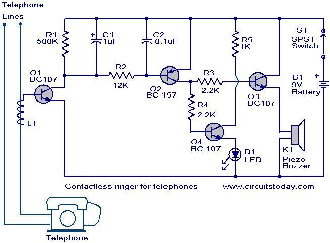
The contactless telephone ringer circuit is designed to produce an audible ring and a visual indication when a call is received. Its primary advantage lies in the absence of direct contact between the telephone line and the circuit, which...

This circuit utilizes digital techniques to implement the frequency-inversion algorithm by digitizing the audio, inverting the sign of every alternate sample, and performing D/A conversion on the resulting data. The outcome is an inverted frequency spectrum. Additionally, the circuit...

This document illustrates the configuration of the high-precision, high-impedance OPA2111 amplifier. The total voltage circuit is designed for a magnification of Av = 10 (1 + 2R2 / R1), achieving a total gain of 1000 times. A gain stage...

This design circuit functions as a sine wave oscillator, providing both sine and square wave outputs across a frequency range from below 20 Hz to above 20 KHz. The oscillation frequency can be easily adjusted by varying a single...