
tuned sine wave oscillator circuit

The sine wave oscillator circuit is designed to generate stable sine and square wave outputs over a wide frequency range, making it suitable for various applications in signal generation and testing. The use of LM111 and LM101A operational amplifiers allows for precise control over the waveform characteristics. The tuning components, R1, R2, R3, C1, and C2, form a feedback network that determines the oscillation frequency. The resistor R3 is particularly critical for fine-tuning, enabling the user to achieve the desired frequency without affecting the overall gain or bandwidth of the circuit.
The operational amplifier's role as a tuned circuit is essential, as it processes the square wave signal generated by the comparator. The feedback loop created by the square wave allows for sustained oscillation, while the Zener diode D1 ensures that the feedback signal remains within a stable amplitude range, preventing distortion in the output waveforms. The combination of R6 and C5 not only assists in initiating the oscillation process but also ensures that the comparator operates effectively within its linear range, promoting consistent performance.
This oscillator circuit is versatile and can be utilized in various applications, including audio signal generation, waveform shaping, and as a clock source for digital circuits. The ability to generate both sine and square waves allows for a wide range of testing and operational scenarios, making this circuit a valuable tool for electronic engineers and designers.This is a design circuit for sine wave oscillators that will provide both a sine and square wave output for frequencies from below 20 Hz to above 20 KHz. The frequency of oscillation is easily tuned by varying a single resistor. This circuit is controlled by two op amp, LM111 and LM101A. This is the figure of the circuit. In this circuit, an opera tional amplifier has function as a tuned circuit, driven by square wave from a voltage comparator. The frequency is controlled by R1, R2, C1, C2, and R3, with R3 used for tuning. Tuning the filter does not affect its gain or bandwidth so the output amplitude does not change with frequency. A comparator is fed with the sine wave output to obtain a square wave. The square wave is then fed back to the input of the tuned circuit to cause oscillation. Zener diode, D1, stabilizes the amplitude of the square wave fed back to the filter input. Starting is insured by R6 and C5 which provide dc negative feedback around the comparator. This keeps the comparator in the active region. [Schematic diagram source: National Semiconductor. Inc] 🔗 External reference
Related Circuits
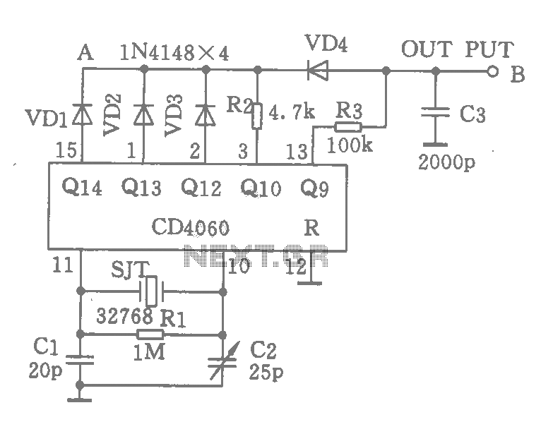
A CD4060 integrated circuit, combined with a 32,768 Hz crystal oscillator, is utilized to create a highly accurate clock source that generates 60 pulses per second. The operation is based on the division of the 32,768 Hz pulse output...
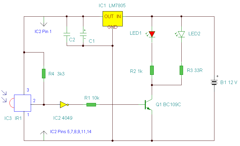
The circuit detects a sudden shadow falling on the light-sensor and sounds the bleeper when this happens. The circuit will not respond to gradual changes in brightness to avoid false alarms. The bleeper sounds for only a short time...

The YD9088 is a bipolar integrated circuit designed for use in mono portable and pocket radios. It is advantageous when minimizing peripheral components, which should be of small dimensions and low cost, is a priority. The circuit incorporates a...
This is an improved IR remote control extender circuit. It has high noise immunity, is resistant to ambient and reflected light and has an increased range from remote control to the extender circuit of about 7 meters. It should...
This modified Hartley oscillator can be utilized to attract new friends or serve as a replacement doorbell. The modified Hartley oscillator is a type of electronic oscillator that generates a continuous waveform, typically a sine wave, using an LC (inductor-capacitor)...
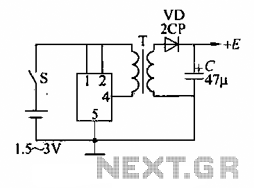
A DC booster circuit is illustrated in the figure, which represents a step-up transformer circuit diagram. The step-up transformer (T) can be utilized to power small transistor radios. The winding ratio can be adjusted to achieve the desired output...