
555 tri-state acousto-optical logic circuit

The circuit described operates in a monostable or astable multivibrator configuration, utilizing the 555 timer's ability to toggle between states based on external inputs. The resistors R4 and R5, along with the capacitor C1, define the timing characteristics of the oscillation. In this setup, R4 and R5 are connected in series to control the charge and discharge cycles of C1, ultimately determining the frequency of oscillation. The output frequency can be calculated using the formula for the astable multivibrator configuration:
\[ f = \frac{1.44}{(R4 + 2R5)C1} \]
This equation indicates that increasing the resistance values or capacitance will decrease the frequency, while decreasing them will increase the frequency.
When probe A is floating, the state of VT1 is crucial; it acts as a switch that either allows or blocks current flow based on the logic level detected. This feature allows for the dynamic control of the 555 timer's operation, enabling it to function as an oscillator when needed or remain inactive to conserve power.
The output at pin 3 of the 555 timer drives an LED, which serves as a visual indicator of the circuit's state. When the timer oscillates, the LED blinks at the determined frequency, providing an audible and visual signal to the user. This circuit can be employed in various applications, such as timers, tone generators, and other signal processing tasks where a controllable output is required based on an external logic level.
Overall, this configuration showcases the versatility of the 555 timer in creating responsive and dynamic electronic circuits, allowing for effective control and monitoring of logic states through simple components.As illustrated, 555 and R4, R5, C1 and so connected as a controllable multivibrator mode, which force reset terminal 4 feet to explore pen, control terminal 5-pin external level high and low logic level input related. When the probe A floating, VT1 off, added to 5 feet voltage Vdd, 555 multi-harmonic oscillator circuit can not afford, was 3 feet high, LED light, silent; when the probe A logic "1" VT1 saturated conduction, 5 feet lower than the potential Vdd, 555 oscillation, the oscillation frequency depends on the value of R4, R5 and C1. Oscillation frequency icon parameter is about 1000Hz, audible signal; when the probe A logic "0", 4 feet since the low, 555 is forced to reset, silent and dark.
Related Circuits
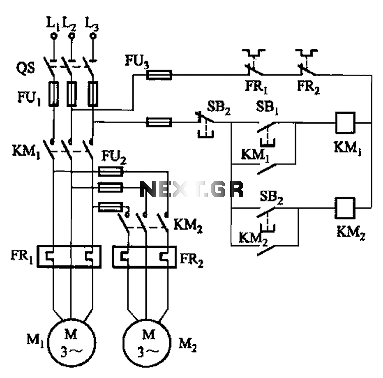
The circuit illustrated in Figure 3-83 demonstrates that the contactor KMi is activated only after it is pulled, which indicates that the motor Mi has started for the first time. Following this, the contactor KM2 is then activated, indicating...
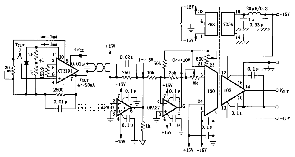
The circuit depicted in the figure features the ISO102 and XTR101 components, forming an isolated remote transmitter circuit equipped with isolated thermocouple cold-junction compensation. The circuit comprises four main parts: the current loop amplifier XTR101, the isolation amplifier ISO102,...
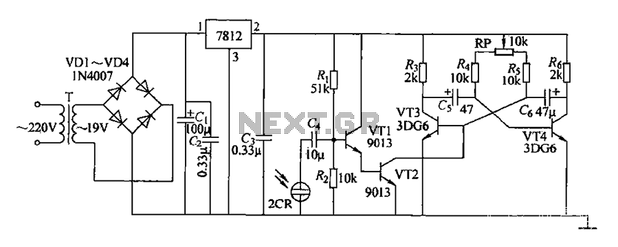
220V AC voltage is transformed by transformer T to 19V. After passing through a full-wave bridge rectifier and filter capacitor C, the voltage is regulated to DC using a 7812 voltage regulator. When the battery indicator light is illuminated,...
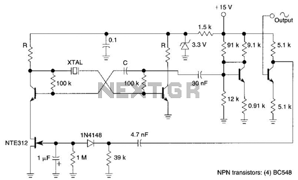
Q1, Q2, and the associated circuitry constitute a modified astable multivibrator where the loop gain is automatically adjusted to the threshold of oscillation by field effect transistor Q3. Q4 amplifies the signal at the collector of Q2 and isolates...
Here are some circuit diagrams for driving relays from a microcontroller. Ensure the use of a 5-volt relay (this refers to the coil, not the load circuit) and verify that the relay has a sufficient rating for the load...
Comprehensive information regarding the RF Field Strength Meter Circuit is available. Users can learn about and download the RF Field Strength Meter Circuit online. The RF Field Strength Meter Circuit is designed to measure the strength of radio frequency (RF)...