
relay circuit diagram

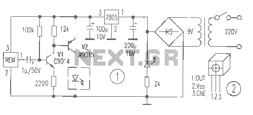
The circuit diagrams for driving relays from microcontrollers typically include essential components such as the microcontroller itself, a relay module, and supporting components like resistors, diodes, and transistors. The microcontroller outputs a control signal to the base of a transistor, which acts as a switch to drive the relay coil. The transistor amplifies the current from the microcontroller, enabling it to control the relay, which can handle higher voltage and current loads.
In the case of a 5-volt relay, the relay coil is connected to the collector of the transistor, while the emitter is grounded. A resistor may be placed between the microcontroller output pin and the base of the transistor to limit the current flowing into the base. A flyback diode is typically connected in parallel with the relay coil to prevent voltage spikes generated when the relay is turned off, which could damage the microcontroller.
For relays that can be directly activated by the microcontroller, such as reed or solid-state relays, the circuit is simplified since no additional components like transistors are required. The microcontroller can switch these relays directly, provided they operate within the microcontroller's current and voltage specifications.
When dealing with AC loads, the relay contacts should be rated for the AC voltage and current being switched. Proper labeling of the relay pins is crucial for ensuring correct connections. It is imperative to construct the AC circuit safely, ensuring that the relay coil is tested and operational before connecting any AC load. Safety precautions must be taken to avoid direct connections of AC voltage to the relay coil, and if there is any uncertainty regarding the circuit, it is advisable to consult with an experienced individual for verification.Here`s are some circuit diagrams for driving relays from a microcontroller. Make sure you`re using a 5-volt relay (this refers to the coil, not the load circuit), and make sure that the relay has a high enough rating for the load that you`re driving. This circuit is necessary if you are using a relay with a coil that needs more power than the micr ocontroller can supply (this includes most miniature electromechanical relays): Some relays (such as reed relays and solid-state relays) have coils that can be switched directly from the microcontroller, in which case you can use a less complex circuit: Finally: if you`re switching an AC device, PLEASE BE CAREFUL. Make sure you`ve got the coil working BEFORE you hook up the AC load. Make sure you have correctly labeled all the pins on the relay NEVER connect AC voltage directly to the relay coil.
Build your AC circuit BEFORE you plug it in. If you`re not sure, ask someone to check it for you first. 🔗 External reference
Related Circuits
This circuit is designed to power a lamp or other appliance for a specified duration of 30 minutes, after which it automatically turns off. It is particularly useful for nighttime reading, as it can turn off a bedside lamp...
This simple circuit, as shown in the schematic diagram, activates a switch using sound. It can be utilized for various applications, such as automatic sound-controlled disco lights or a car's LED light show. The transistor Q1 amplifies the audio...
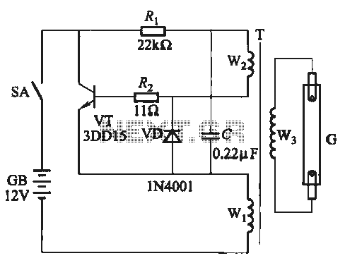
A self-excited transistor inverter circuit is designed for improved performance and features a relatively simple schematic. It is suitable for driving fluorescent lamps with a power rating between 8 to 40 watts. This inverter can operate stably even when...
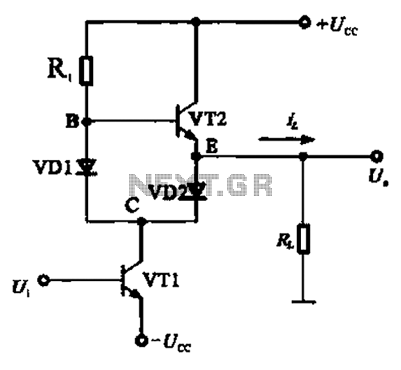
A Class AB output stage circuit is coupled with diodes, as illustrated in Figure 10-8. The static bias circuit for transistor VT1 (not shown) is adjusted so that the output at point E is at ground DC voltage UE....
The laser-pointer detection circuitry is capable of identifying when a laser light is directed at a specific photosensor. If the laser targets the top sensor, the comparator chip outputs a high signal. Conversely, if the laser is aimed at...
The receiver provides two TV signals, one for the living room and another for the bedroom, along with a satellite receiver. Watching television in the bedroom is convenient in Taiwan; however, when watching television in the living room, it...