
555 wailing siren

The wailing siren circuit is designed to create an audio effect that simulates the sound of a siren, commonly used in alarms or warning signals. The core components of this circuit are the two 555 timer ICs, which are configured in astable mode to generate a square wave signal.
The first 555 timer is responsible for generating a frequency that modulates the pitch of the sound produced by the loudspeaker. By adjusting the resistors and capacitors connected to this timer, the frequency can be altered, allowing the pitch to increase and decrease over time. This modulation creates the characteristic wailing sound of the siren.
The second 555 timer serves as a control circuit that influences the duty cycle of the output waveform from the first timer. By varying the duty cycle, the overall volume of the sound can be adjusted, enhancing the siren effect. The output from the first 555 timer is fed into the loudspeaker, which converts the electrical signal into audible sound.
To construct the circuit, the following components are required: two 555 timer ICs, a loudspeaker, resistors, capacitors, and a power supply. The circuit can be built on a breadboard for prototyping. The schematic diagram should clearly show the connections between the components, including the power supply connections, the configuration of the 555 timers, and the loudspeaker output.
Proper attention should be given to component values, as they will determine the frequency range and modulation characteristics of the siren. It is advisable to experiment with different resistor and capacitor values to achieve the desired sound effect. Safety precautions should be taken when working with electronic components, particularly when connecting to the power supply.
Overall, this wailing siren circuit provides an interesting project that demonstrates the versatility of the 555 timer ICs and offers a practical application for sound generation in electronic designs.In this tutorial you will build a wailing siren that plays a tone that increases and decreases in pitch. The circuit uses two 555 ICs and a loudspeaker.. 🔗 External reference
Related Circuits

The 555 integrated circuit (IC) is configured in monostable mode of operation. In this mode, the output remains LOW (0V) when there is no trigger input. When a trigger is applied through pin 2, the output switches to HIGH...

Wireless stepper motor speed control project using a laser and IC555. This project provides insights into the fundamentals and circuit construction for controlling the speed of a wireless stepper motor utilizing a laser and the IC 555 timer. The project...
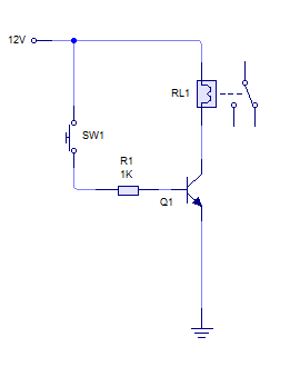
A relay is activated by grounding the low side using an NPN transistor. A pushbutton is intended to operate the transistor, thereby energizing the relay for approximately 500 milliseconds before deactivating it, while ignoring any continuous button press. Although...
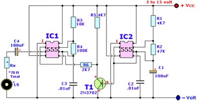
Browse home alarm circuit explanation latest schematic siren wailing with latest Wailing Alarm Siren circuit schematic with explanation. The loudspeaker LS and the resistor marked Rx should be together 75 ohms. If a standard 8-ohm speaker is used, then...

These novel relay driver circuits can activate a relay with a coil voltage rating that is double the Vcc. After activation, the relay armature is held in place. The relay driver circuits described are designed for applications requiring the control...
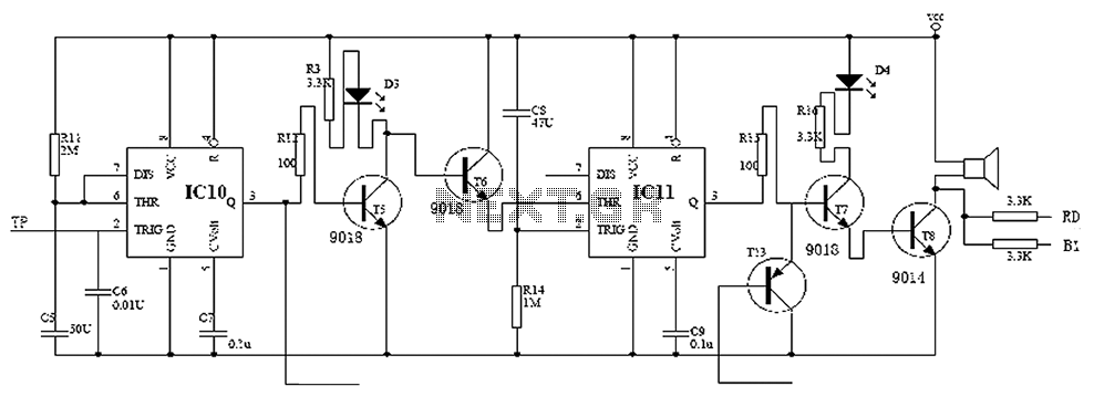
Child lock voltage comparator 555 monostable circuit, a counter, JK flip-flop, UPS power supply design digital logic circuit, electronic door control, and various additional circuitry to ensure the safety circuit can operate with a high safety factor. The circuit...