
5v 1a power supply using lm2575

In the context of power regulation, the use of PWM is a critical technique that allows for efficient control of power delivery while minimizing heat dissipation. The choice of the transistor or MOSFET is crucial; a device with a lower on-state voltage drop will inherently produce less heat, which is advantageous for thermal management in power applications. When implementing PWM, the frequency and duty cycle are vital parameters. A frequency of 100 kHz is commonly used as it strikes a balance between efficient switching and manageable losses.
The inductors and capacitors used in the smoothing stage play a pivotal role in filtering the output, transforming the pulsed waveform into a more stable DC signal. The inductor stores energy during the on phase and releases it during the off phase, while the capacitor smooths out voltage fluctuations. The integration of a Schottky rectifier like the 1N5817 is essential due to its fast switching characteristics and low forward voltage drop, which minimizes additional losses during the rectification process.
Overall, this combination of PWM control, careful selection of components, and effective filtering techniques enables the design of efficient power regulation systems suitable for various electronic applications.A Power Transistor which is having a drop of 4 Volts across it and passing 3 amps thru it, may dissipate around 12 Watts of Heat, This is the problem in Series Regulators. While a Saturated Transistor or Mosfet with 1 Volts across and 3 Amps Thru will be just 3 Watts. But then a fully on transistor or mosfet cannot be controlled or regulated, for that we turn it ON and OFF very fast so that the right amount of current or voltage is delivered. The way this is done is PWM - Pulse Width Modulation. In this the mosfet or transistor is switched ON-OFF at say 100 kHz, but the ON duration is varied to control the output. The longer the duration of ON time more energy or punch is transferred. Switching losses will be present depending on how fast the rise and fall times of the pulses are. The Pulsed AC or Chopped DC can be smoothed to the Average with Inductors and Capacitors. The reactive pulses of the Inductor has to be absorbed by a Schottky Rectifier 1N5817 - 20V-1A fast switching diode with low switching losses.
🔗 External reference
Related Circuits
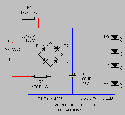
The circuit provides sufficient illumination suitable for reading purposes. Capacitor CX, in conjunction with diodes D1 through D4, constitutes the AC step-down circuit. CX lowers the high voltage AC from the mains to a low voltage AC, which is...
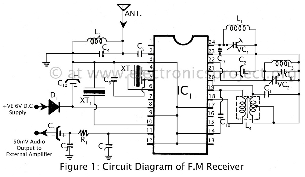
Communication in the FM band is straightforward. This circuit diagram illustrates a powerful FM receiver utilizing a single integrated circuit (IC) that receives frequencies from 88 MHz to 108 MHz within the FM band. The FM receiver circuit described operates...
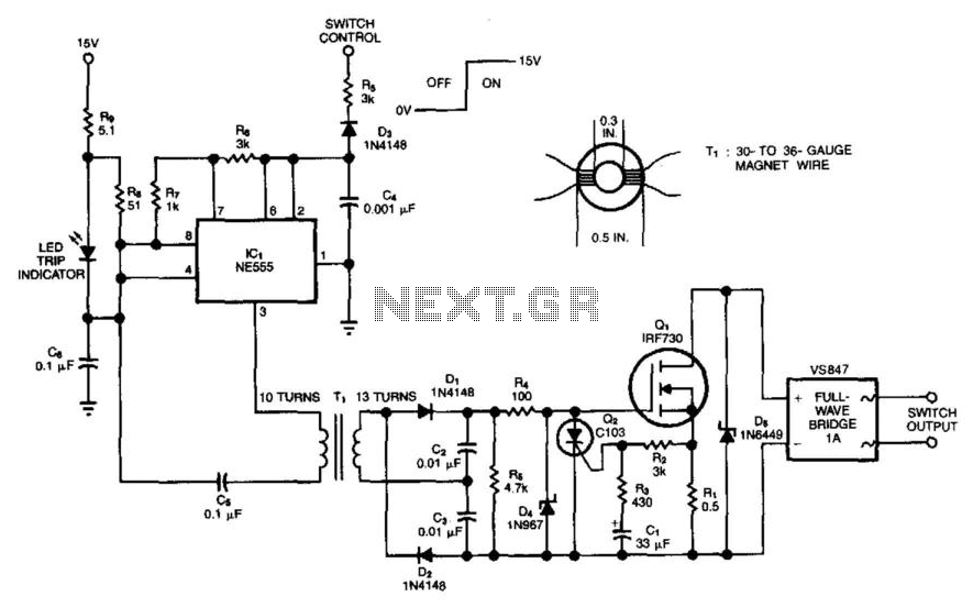
This solid-state switch detects and interrupts an overcurrent condition within 2 microseconds. It allows the circuit to float. IC1 operates at 150 kHz, and the full-wave doubler D1/D2 provides 15 V to the gate of Q1. An overcurrent sensed...
A 30W Class AB power amplifier circuit diagram utilizes a power transistor. To set up the amplifier, adjust the variable resistor R1 to its maximum value and R12 to zero. After completing this setup, activate the amplifier. Adjust R1...
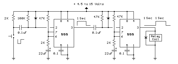
This toggle circuit utilizes two 555 timers configured as inverters. Pins 2 and 6 serve as the threshold and trigger inputs for the first timer, while pin 5 provides the output. The output at pin 5 will consistently reflect...
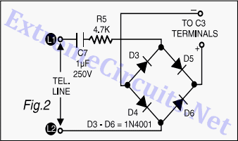
A circuit for a bicycle horn utilizing a low-cost telecom ringer chip is presented. This design can be powered by a bicycle dynamo, eliminating the need for frequently replaced batteries. The circuit includes a half-wave voltage-doubler section formed by...