
simple and powerful F.M. Receiver

The FM receiver circuit described operates within the frequency range of 88 MHz to 108 MHz, which encompasses the standard FM broadcast band. The primary component of this design is a single integrated circuit (IC), which simplifies the overall design while maintaining effective performance.
The circuit typically includes an antenna for signal reception, which captures the FM signals transmitted from local radio stations. The received signals are then fed into the IC, which is responsible for demodulating the FM signal and converting it into an audio output.
Key components of the circuit may include:
1. **Antenna**: A suitable antenna is essential for optimal signal reception. A simple wire antenna can often suffice for this frequency range.
2. **Tuning Circuit**: A variable capacitor or a potentiometer may be used in conjunction with inductors to create a tuning circuit that allows the user to select the desired frequency within the FM band.
3. **Integrated Circuit (IC)**: The IC is the heart of the receiver. It typically contains all necessary circuitry for demodulation, amplification, and audio output. Commonly used ICs for FM receivers include the TEA5767 or the LM386, among others.
4. **Audio Output Stage**: After demodulation, the audio signal is usually weak and requires amplification. An audio amplifier circuit may be included to boost the signal to a level suitable for driving speakers or headphones.
5. **Power Supply**: The circuit requires a stable power supply, which can be provided by batteries or a DC power adapter, depending on the application.
The design of this FM receiver circuit emphasizes simplicity and efficiency, making it suitable for educational purposes and hobbyist projects, as well as for basic radio communication applications. Proper layout and component selection are crucial for minimizing noise and ensuring clear audio output. Overall, this circuit serves as an effective solution for receiving FM broadcasts within the specified frequency range.Communication in F.M. band is easy.circuit diagram with description of Power Full F.M. receiver using single IC receive 88 MHz to 108 MHz frequency in F.M. band,. 🔗 External reference
Related Circuits

This lie detector circuit provides two readings: one for difficult questions and another for the subject's general emotional state. Two flexible, uninsulated wires wrapped around the fingers or wrist can serve as electrodes. Each change in resistance, and consequently...
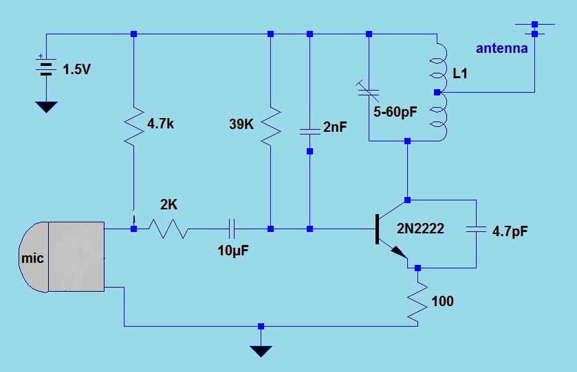
This simple FM (frequency modulation) transmitter is powered by a 1.5V battery and utilizes a single frequency determined by the transmitter transistor. It is controlled by an LC resonant circuit and operates within a frequency range of 80 to...
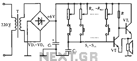
The circuit includes resistors Rp1 to Rp13, which serve dual purposes: they scale the resistance for the keyboard and function as timing resistors for the oscillator. Capacitor C2 acts as a wide discharge capacitor, while switches S1 to S13...
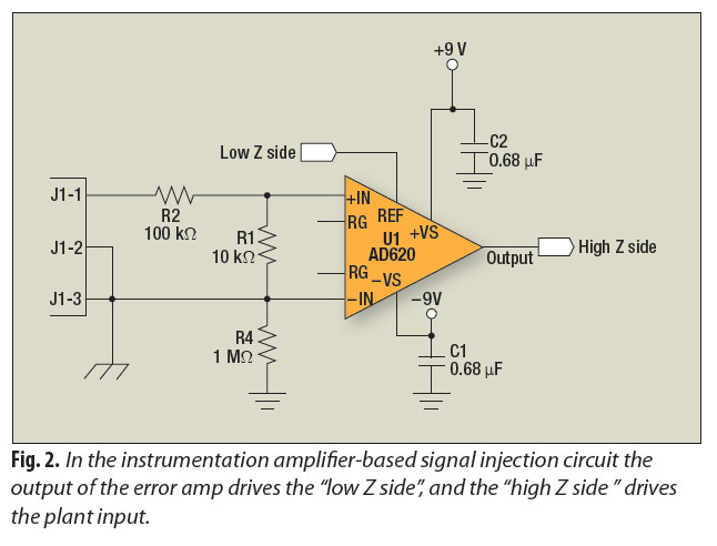
A signal-injection circuit for control-loop analysis is flat from DC to 200 kHz, isolated from chassis ground, and easily constructed with a readily available instrumentation amplifier. The signal-injection circuit is designed to facilitate control-loop analysis by providing a stable and...
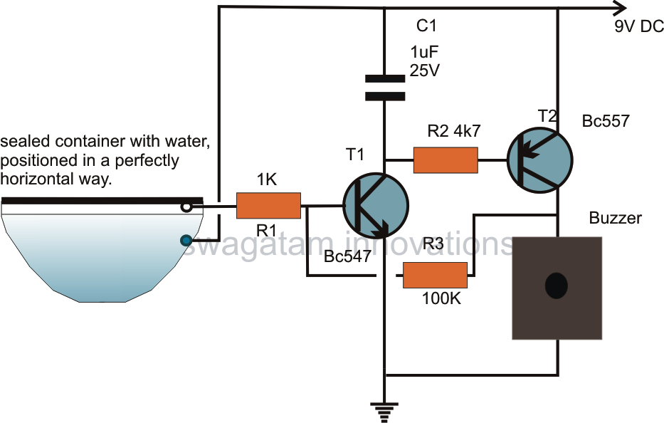
The article presents a circuit concept that features an innovative method for detecting minimal shocks caused by potential earthquake tremors. This circuit is highly sensitive, capable of detecting tremors of magnitude 4 on the Richter scale, while remaining unaffected...
MRFICl505R2 is a 1.575GHz GPS downconverter chip. It integrates a mixer, VCO, PLL, crystal oscillator, A/D converter, loop filter, and other circuits. The MRFICl505R2 IF output frequency is 4.1MHz, with a typical conversion gain of 105dB, an operating voltage...