
Dual Regulator Handles Two Input Voltages

The circuit illustrated in Fig 1 is designed to accommodate the power requirements of mixed-voltage systems, supplying both 3.3V and 5V outputs. This dual-voltage capability is essential for integrating newer 3.3V logic devices alongside legacy 5V components, thus facilitating a smooth transition during upgrades or system enhancements.
The circuit typically employs a voltage regulator capable of stepping down a higher input voltage, such as 12V or 9V, to the required output levels. A linear voltage regulator, such as the LM317 for adjustable outputs or the LM7805 for fixed 5V output, can be utilized for this purpose. For the 3.3V output, a low-dropout (LDO) regulator is preferred to minimize power loss and heat generation, especially when the input voltage is close to the desired output voltage.
Input capacitors are recommended at the input of each regulator to stabilize the voltage and filter out noise, while output capacitors help maintain voltage stability during load changes. It is also advisable to include bypass capacitors close to the power pins of the devices being powered to ensure clean power delivery and reduce the effects of electromagnetic interference (EMI).
In addition to the regulators, the circuit may include protection features such as fuses or resettable polyfuses to prevent damage from overcurrent conditions. Furthermore, the design should incorporate adequate heat sinking for the regulators, particularly if the load current is substantial, to ensure reliable operation without thermal shutdown.
Overall, this circuit design effectively bridges the voltage gap between modern and legacy devices, ensuring compatibility and reliable performance in mixed-voltage environments.The circuit in Fig 1 supplies both 3.3 and 5V to transitional circuits that employ both the new 3.3V and older 5V devices. Additionally, because the regul.. 🔗 External reference
Related Circuits
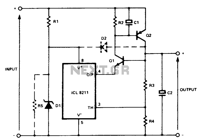
In the circuit, Q1 and Q2 are connected in the classic SCR or thyristor configuration. When higher input voltages or a minimal component count are required, the thyristor boost circuit can be utilized. The thyristor operates in a linear...
As power supply switching frequencies increase, higher loop crossover frequencies are necessary to keep pace with the escalating load transient slew rate demands and to reduce the number and size of filter components. For voltage-mode-controlled supplies, the voltage loop...

Author Mazi Hosseini describes a simple, low-cost voltage-controlled current source using two operational amplifiers that provides a good range of current and maximum load. The circuit described by Mazi Hosseini utilizes two operational amplifiers (op-amps) to create a voltage-controlled current...
For hobbyists or professional electronic engineers engaged in various electronic experiments, troubleshooting, or testing, it is essential to provide a wide range of variable options. In electronic engineering, the ability to manipulate and measure a wide range of variables is...
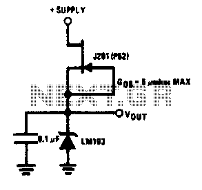
This simple reference circuit provides a stable voltage reference that is nearly free from supply voltage noise. Typical power supply rejection exceeds 100 dB. The described voltage reference circuit is designed to deliver a consistent output voltage while minimizing the...
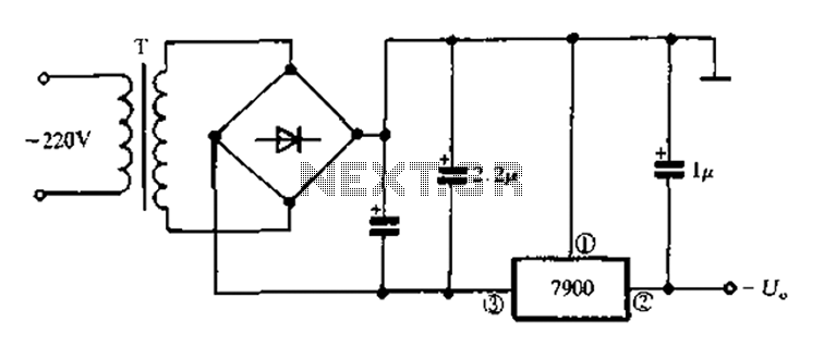
7900 series three-terminal fixed negative output voltage regulator circuit The 7900 series comprises a range of three-terminal fixed negative voltage regulators designed to provide stable output voltages. These regulators are specifically engineered to deliver a consistent output voltage, which is...