
5V Regulated Power SupplyCircuit

This circuit functions as a reliable +5V power supply, ideal for digital electronics projects. The core of the circuit is the 7805 voltage regulator, which maintains a stable output voltage of +5V. The input voltage to the regulator should be sourced from a wall transformer that is capable of delivering a voltage higher than +5V, typically in the range of +8V to +12V, to ensure proper regulation. The regulator can supply up to 1A of current with sufficient heat dissipation, which is achieved through the use of a heat sink.
The circuit should include a pair of capacitors at the input and output of the regulator. A 0.33 µF capacitor is recommended at the input to filter out high-frequency noise, while a 0.1 µF capacitor at the output helps stabilize the output voltage. Additionally, a larger electrolytic capacitor, typically in the range of 10 µF to 100 µF, can be placed at the output to provide better transient response and further smooth the output voltage.
Thermal protection is an essential feature of this circuit, as the 7805 regulator can become hot under load. It is advisable to include a thermal cutoff switch or a fuse in the circuit to prevent overheating. Overload protection can be implemented using a simple current-limiting resistor or a more sophisticated solution involving a PTC resettable fuse.
For users requiring different output voltages, the circuit can be easily adapted by swapping the 7805 with other regulators from the 78xx series, such as the 7812 for +12V or the 7809 for +9V. Each variant has a specific output voltage indicated by the last two digits of its part number. When modifying the circuit for different output voltages, it is crucial to recalculate the input voltage requirements based on the new output voltage to maintain proper operation and ensure that the input voltage remains at least 3V above the desired output voltage.
Overall, this circuit design provides a straightforward and effective solution for powering digital electronics, ensuring stable voltage and current while offering flexibility for various applications.This circuit is a small +5V power supply, which is useful when experimenting with digital electronics. Small inexpensive wall tranformers with variable output voltage are available from any electronics shop and supermarket.
Those transformers are easily available, but usually their voltage regulation is very poor, which makes then not very usable for digital circuit experimenter unless a better regulation can be achieved in some way. The following circuit is the answer to the problem. This circuit can give +5V output at about 150 mA current, but it can be increased to 1 A when good cooling is added to 7805 regulator chip. The circuit has overload and thermal protection. The capacitors must have enough high voltage rating to safely handle the input voltage feed to circuit.
The circuit is very easy to build for example into a piece of veroboard. If you need other voltages than +5V, you can modify the circuit by replacing the 7805 chips with another regulator with different output voltage from regulator 78xx chip family. The last numbers in the the chip code tells the output voltage. Remember that the input voltage muts be at least 3V greater than regulator output voltage ot otherwise the regulator does not work well.
🔗 External reference
Related Circuits
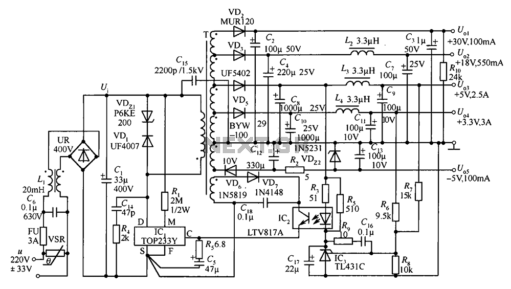
A 35W switching power supply circuit designed for a set-top box output is depicted in Figure 5. It features five distinct voltage outputs: Uo1 (+30V, 100mA), Uo2 (+18V, 550mA), Uo3 (+5V, 2.5A), Uo4 (+3.3V, 3A), and Uo5 (-5V, 100mA)....
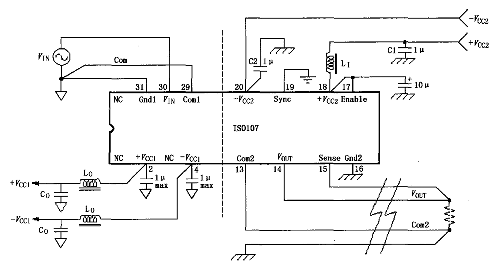
The basic connection circuit for the ISO107 signal and power supply is illustrated. Each power supply terminal must include a bypass filter. If the output current from the isolated power supply exceeds 15 mA, it is advisable to utilize...
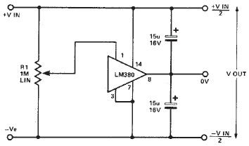
A simple split power supply circuit can be designed using the schematic diagram based on the LM380 audio power integrated circuit (IC). The output voltage regulation is dependent on the circuit feeding the LM380. The power dissipation is approximately...
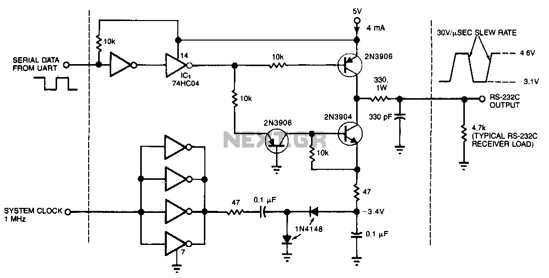
This circuit draws only 4 mA from a 5-V supply while driving a standard RS-232C receiver. The system clock drives a de-de converter that produces -3.4 V. The frequency can range from 0.5 to 8 MHz, but a range...
The two circuits demonstrate the process of opening a relay contact shortly after the ignition or light switch is turned off. The capacitor becomes charged, and the relay remains closed until the voltage at the diode anode reaches +12...
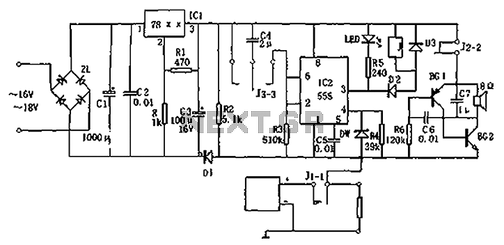
Circuit diagram for a DC power supply protection circuit. The device includes a buck rectifier power supply, a monostable delay circuit, a relay control circuit, and an audio feedback oscillation circuit. The entire circuit operates with a DC voltage...