
power off time delay relay

The described circuits utilize a relay and a capacitor to create a delayed opening mechanism for the relay contacts. When the ignition or light switch is turned off, the voltage supply to the circuit is interrupted. Initially, the capacitor holds a charge, which keeps the relay in a closed state. The relay operates as a switch that controls the flow of current to a load, such as lights or other electrical devices.
As the circuit operates, the diode plays a crucial role by allowing current to flow in one direction while blocking reverse current. When the ignition or light switch is turned off, the voltage at the anode of the diode begins to decrease. The capacitor discharges through the relay coil, maintaining the relay in the closed position for a brief period. This delay allows for a controlled shutdown of the connected load, preventing abrupt disconnection and potential damage to sensitive components.
The time it takes for the voltage at the diode anode to drop to +12 volts is determined by the capacitance value of the capacitor and the resistance in the circuit. A larger capacitance will result in a longer delay, while a smaller capacitance will reduce the delay time. The values of these components should be selected based on the specific application requirements, ensuring that the relay opens at the desired moment after the switch is turned off.
This circuit configuration is commonly used in automotive applications where it is beneficial to keep lights on for a short duration after the vehicle is turned off, enhancing safety and convenience. Proper implementation of these circuits can improve user experience and protect electrical components from voltage spikes or sudden disconnections.The two circuits illustrate opening a relay contact a short time after the ignition or ligh switch is turned off. The capacitor is charged and the relay is closed when the voltage at the diode anode rises to +12 volts..
🔗 External reference
Related Circuits
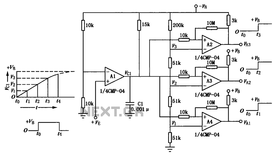
A multi-stage delay circuit is presented in this schematic. The operational amplifiers are configured as comparators. Operational amplifier A1 operates when the voltage at the inverting input exceeds + VE. As the voltage at the inverting input of operational...
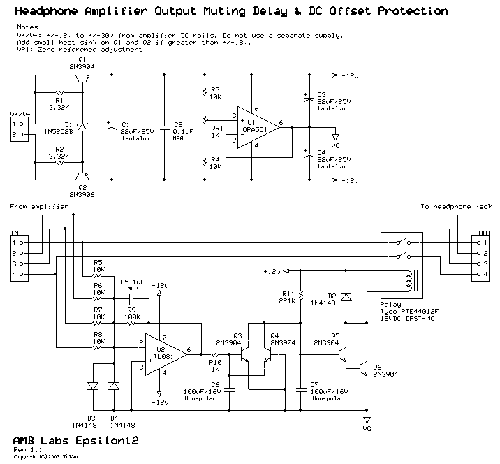
A low-pass filter is a stable state-space system that has an input and produces an output. If the input is a quasi-periodic signal, the output will be the same quasi-periodic signal with a phase shift. The key difference is...
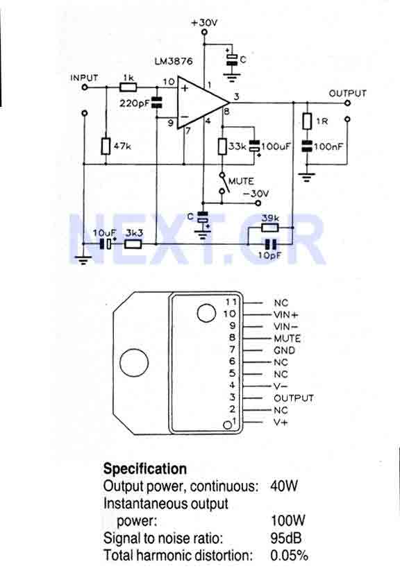
This Circuit is based on the LM3876. A 11-pin plastic package IC with high performance audio power amplifier, an output mute function which can be used to eliminate switch-on and switch-off "thumps" to the loudspeaker load. It is capable...
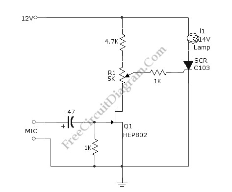
This simple circuit illustrated in the schematic diagram activates the switch using sound. It can be utilized for various applications, such as automatic (sound-controlled) disco lights or car LED light shows. The transistor Q1 amplifies the audio from the...

This is an adjustable and regulated power supply with an output voltage range of 3V to 30V and a current supply capability of up to 3A. This circuit is equipped with short circuit protection and overload protection. The adjustable power...
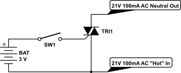
Control a furnace using a 3.3V microcontroller. The furnace operates by connecting a common 21V AC "hot" line to one of two AC "neutral" output lines: Fan and Heat. When connected, they have relatively low current flow, approximately 100mA....