
5V USB interface power supply / charger circuit

The USB charger power supply circuit typically consists of several key components arranged to convert the AC input voltage to a stable DC output voltage suitable for charging devices. The primary input stage includes a transformer that steps down the AC voltage from the mains supply to a lower voltage. This transformer is essential for isolating the high-voltage AC from the low-voltage DC side, ensuring safety during operation.
Following the transformer, a rectifier circuit is employed to convert the AC voltage to pulsating DC. This is usually achieved using a bridge rectifier configuration, which consists of four diodes arranged in a bridge formation. The rectifier output is then smoothed using a filter capacitor, which reduces the ripple voltage and provides a more stable DC output.
The voltage regulation stage is critical in maintaining a consistent output voltage of 5V. This is often implemented using a linear voltage regulator, which can handle the input voltage and provide the desired output. In this design, if a higher output current is required, replacing the transistor Q1 with a 13003 can enhance the current handling capability, allowing for a longer duration of higher current output without overheating or failure.
The output stage includes a USB connector, allowing for easy connection to various devices such as MP3 and MP4 players. The circuit is designed to meet the USB power delivery specifications, ensuring compatibility with a wide range of devices. Additionally, safety features such as overcurrent protection and thermal shutdown may be integrated to protect both the charger and the devices being charged.
Overall, this USB charger power supply circuit is a reliable solution for charging portable electronic devices, providing the necessary voltage and current levels while ensuring safety and efficiency.The USB Charger power supply,should be used inMP3MP4 charger ,which input AC160-240V, 50/60Hz, rated output: DC 5V , 250mA (if you want long-term greater current output, replace Q1 to 13003).. 🔗 External reference
Related Circuits
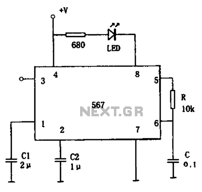
The FM demodulation circuit is illustrated in Figure 567. The FM signal is input at pin 3, and the demodulated signal is output from pin 5. The center frequency of the FM demodulation circuit is determined by the formula...
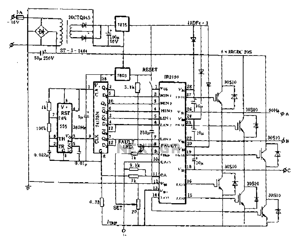
The application of the aforementioned advantages allows the IR2130 to be effectively utilized for DC cut crossing speed, DC servo systems, three-phase power inverters, and switching power supplies. Additionally, it is applicable in inverter power supplies, uninterruptible power supplies...
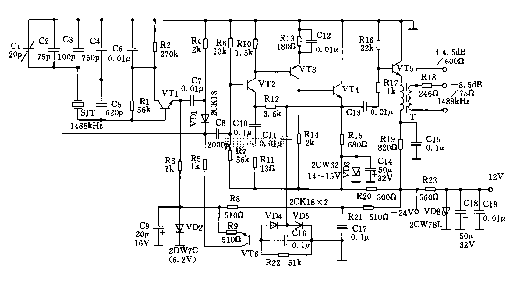
A 1488 kHz master oscillator quartz crystal resonator is utilized for frequency stabilization. The output from the frequency divider provides three different square wave signal outputs at 4 kHz, 12 kHz, and 124 kHz. The circuit includes transistors VT1,...
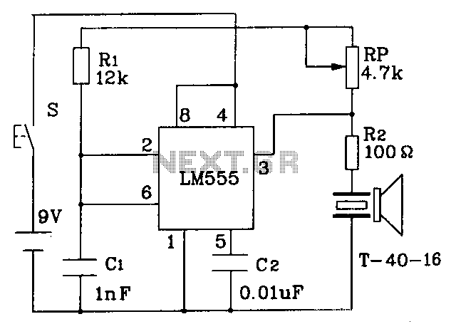
The circuit operates at a distance of 3 feet from the oscillating pulse output of a 555 timer generating a 40kHz signal, driving a T-40-16 transducer to emit ultrasonic signals at the same frequency. The circuit is powered by...
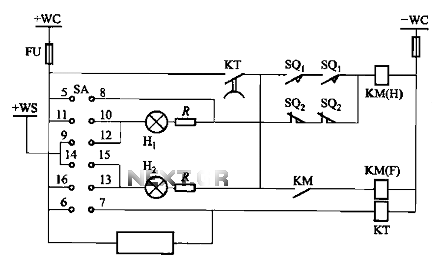
The BT9404 is a de-excitation type switch utilized with CJ4-S contactors and JT3-21/3-type electromagnetic relays. The control circuit is depicted in Figure 7-55. The KM contactors used are CJ4-S, while the time relay is the JT3-21/3. The SA component...
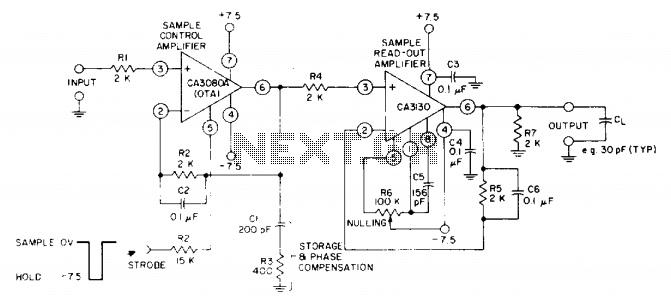
The circuit utilizes a CA3130 BiMOS operational amplifier as the sample-readout amplifier for the storage capacitor C1, while a CA3080A serves as the sample-control amplifier. Applications in linear systems that temporarily store analog data encompass digital voltmeter (DVM) systems,...