
5W RF power amplifier

The circuit features a carefully organized layout designed for efficient integration onto a printed circuit board (PCB). The numbered components facilitate assembly and troubleshooting by providing clear identification for each part.
C5 and C8 are specified as disc ceramic capacitors, known for their stability and reliability in various applications. These capacitors are typically used in high-frequency circuits due to their low equivalent series resistance (ESR) and minimal inductance. The choice of ceramic capacitors helps in ensuring that the circuit maintains performance across a wide range of frequencies.
C6 and C7 are designated as tantalum or electrolytic capacitors. Tantalum capacitors are preferred for their high capacitance per volume and stable electrical characteristics, making them suitable for applications requiring compact size and high reliability. Alternatively, electrolytic capacitors may be used, which are generally larger but offer significant capacitance values. The selection between these types will depend on the specific voltage ratings and capacitance values required for the circuit operation.
Resistors R1, R2, and R3 are classified as 1/4 W carbon composition resistors. These resistors are known for their ability to handle transient voltages and provide reliable performance in various circuit conditions. Carbon composition resistors are often utilized in applications where high stability and low noise are essential.
The circuit design also includes the option to substitute silver-mica capacitors for polystyrene (P) types. Silver-mica capacitors are highly stable and exhibit low loss characteristics, making them suitable for high-frequency applications. This substitution allows for flexibility in component selection based on availability and specific performance requirements.
Impedance transformation ratios are indicated above transformers T1 and T2. These transformers play a crucial role in matching the impedance between different stages of the circuit, ensuring optimal power transfer and minimizing signal reflections. The transformation ratios can be critical in applications such as audio amplification, RF transmission, and other signal processing tasks, where impedance matching is essential for maintaining signal integrity.
Overall, this circuit design incorporates a variety of components selected for their specific electrical characteristics, ensuring reliable performance and adaptability in various electronic applications.Numbered components are so designated for PC-board layout purposes. C5 and C8 are disc ceramic. C6 and C7 are tantalum or electrolytic. Rl, R2 and R3 are Vi W carbon composition resistors. Silver-mica capacitors may be substituted for polystyrene (P) types. Impedance transformation ratios are shown above Tl and T2.
Related Circuits

This is a circuit for Closed-Loop Automatic Power Control for RF Applications. The circuit utilizes a log detector (AD8318) and a variable gain amplifier (VGA) (ADL5330). The Closed-Loop Automatic Power Control (APC) circuit is designed to maintain a consistent output...
This is a wideband shortwave (SW) antenna amplifier. The frequency range spans from 1 to 30 MHz, featuring a medium gain of 15 dB. The input stage utilizes an MPF102 transistor. The wideband shortwave antenna amplifier is designed to enhance...
The LV2282VA is an FM Transmitter integrated circuit (IC). The multiplex (MPX) block generates a stereo modulated composite signal from left (L) and right (R) audio inputs. The radio frequency voltage-controlled oscillator (RF VCO) incorporates an FM modulation function....
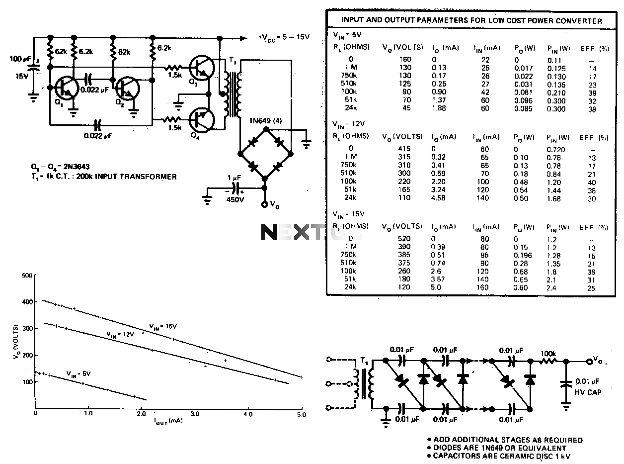
This circuit consists of an astable multivibrator driving a push-pull pair of transistors into the transformer primary. The multivibrator frequency should equal around 1 or 2 kHz. For higher DC voltages, voltage multipliers on the secondary circuit have been...
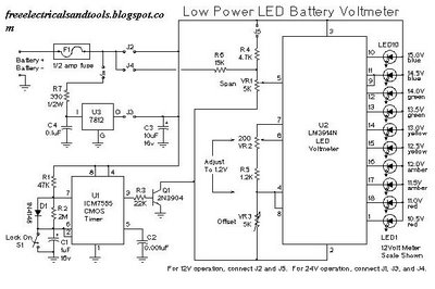
This is a low power voltmeter circuit designed for use with alternative energy systems that operate on 12V and 24V batteries. The voltmeter features an expanded scale that indicates small voltage steps within the 10 to 16 volt range...
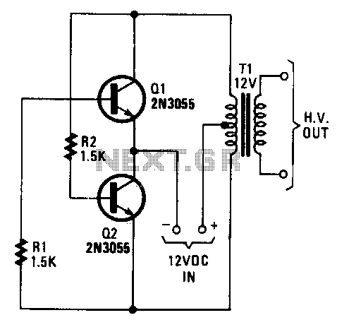
The transformer can be any 6.3 or 12.6 V type. Apply the 12-V DC input so the positive goes to the transformer's center tap and the negative goes to the two transistor emitters. Any bridge-type rectifier and filter can...