
low power led battery voltmeter

The voltmeter circuit is an effective solution for monitoring battery voltage in alternative energy applications, providing a balance between functionality and efficiency. The use of an expanded scale allows for precise voltage readings, crucial for battery management in renewable energy systems. The design considerations, such as low power consumption, adjustable blinking rates, and LED color options, enhance usability and adaptability to various environments. The choice of timer IC significantly influences the circuit's efficiency, making the CMOS ICM7555 a preferred option for applications with limited power resources. The inclusion of protective components like the fuse ensures reliability and safety, making this circuit a robust choice for users seeking to monitor battery health in off-grid or alternative energy scenarios. Proper calibration and component selection will ensure optimal performance and longevity of the voltmeter circuit in its intended applications.This is a low power voltmeter circuit that can be used with alternative energy systems that run on 12 and 24 volt batteries. The voltmeter is an expanded scale type that indicates small voltage steps over the 10 to 16 volt range for 12 volt batteries and over the 22 to 32 volt range for 24 volt batteries.
Power consumption can be as low as 14mw wh en operated from 12V and 160mw when operated from 24V. It is possible to set the meter to read equal steps across a variety of upper and lower voltages. The meter saves power by operating in a low duty-cycle blinking mode where the LED indicators are only on and consuming power briefly during a repeating 2 second cycle. The circuit may be switched to a high power mode where the active LED stays on at all times. Different colored LEDs may be used for the voltage level indicator, this allows the battery state to be read in the dark.
With the new blue LEDs, it is possible to have a nice looking rainbow of colors using two each of red, amber, yellow, green, and blue LEDs. The circuit will also work with inexpensive and common red LEDs. If the circuit is to be used in sunlight, ultra-bright LEDs should be used, although even those may be hard to read without some kind of sun shield.
The circuit may be built with either the CMOS ICM7555 timer or the more common bipolar 555 timer. The 7555 timer will provide much more efficient operation and should be used for systems with small batteries. The heart of the circuit is the LM3914N dot-bar volt meter IC, U2. This chip is operated in the expanded-scale mode so that the circuit responds in the 10-16V range. U2 outputs a steady voltage on pin 7 from the internal voltage reference. This is fed via voltage dividers VR2 and R5 to the internal reference input pins to set the range that the meter is sensitive to.
The measured voltage is fed in on pin 5 via the voltage divider consisting of R4 and VR1. This divider scales the input voltage down to a range that is useful to the IC. The U2 positive supply is connected to pin 3 which is nominally 12V. The U2 negative supply is switched on momentarily via transistor Q1, this switching action is what makes the circuit efficient since U1 (ICM7555) consumes a mere 0. 34 ma while U2 consumes around 18ma with one LED on. The ICM7555 timer, U1 is wired to run in a free-running mode with a narrow pulse width square wave output.
The duty-cycle of U1 is controlled by the ratio of R1 and R2. R2 may be adjusted to a smaller value if faster blinking is desire, a potentiometer may be substituted for R2 if a rate adjustment is desired. R1 may be increased if a longer on-time is desired. Changes in R1 and R2 will affect the average current that the circuit consumes. The frequency of oscillation is determined by C1, R1, and R2. C1 may be either an electrolytic or poly capacitor, if an electrolytic part is used, be sure to connect the positive terminal to U1 pins 6 and 2 and the negative terminal to ground.
The output of the timer IC is fed through current limiting resistor R3 to transistor Q1 which controls power to U2. Capacitor C2 filters the control voltage input to U1 and capacitor C3 provides DC filtering for the whole circuit.
When the lock-on switch across capacitor C1 is closed, the output of the timer remains on, thus enabling the U2 circuitry and increasing the current drain to 18mA. The reason the switch is not simply wired across the transistor is to keep the negative supply to U2 the same as when the circuit is pulsed on.
This maintains the same calibration on the LEDs in both modes because the transistors voltage drop is always part of the circuit. Last, but not least, fuse F1 protects against the potential for fire hazard should the circuit become shorted out.
The average current is calculated by adding the constant current required by U1 with the product of the current from U2 times the duty cycle, see the specifications for details. To operate 🔗 External reference
Related Circuits
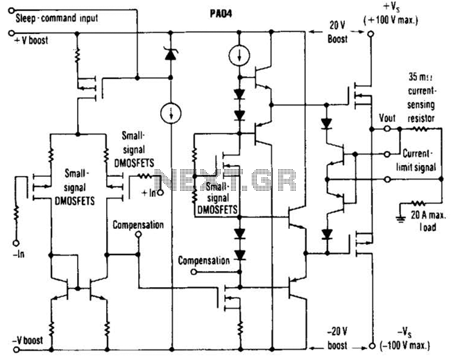
This circuit from Apex Microtechnology can deliver 180 V peak-to-peak at 90 kHz into a 4-ohm load. The PA04 can deliver 400 watts RMS into an 8-ohm load with low total harmonic distortion at frequencies exceeding 20 kHz. The circuit...

I will also explain how you can build a 1.5W PA transmitter. The project will include PCB, components and instructions how to make coils, assembly and testing. First let's discuss and learn about the RMS value of a sine...
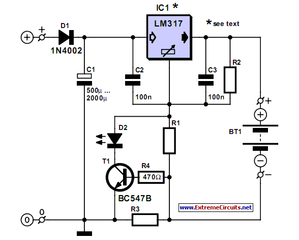
A simple NiCd charger can be constructed using readily available components and an economical LM317 or 78xx voltage regulator. The design incorporates a current limiter made up of resistor R3. The proposed NiCd charger circuit utilizes an LM317 or a...
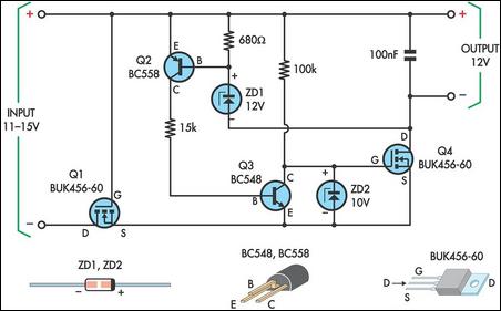
This circuit is designed to power a laptop computer using a solar power setup. The computer requires 12V at 3.3A. The circuit employs a linear regulator with a MOSFET (Q4) as the series pass device. A 100kΩ resistor provides...
The following touch switch circuit utilizes a CA3240 dual BiMOS operational amplifier to detect small currents flowing between the contact points on a touch plate. The touch switch circuit employs a CA3240 dual BiMOS op-amp, which is known for...
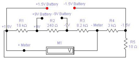
The circuit diagram of a DC battery tester designed by Matthew B. This circuit can measure DC batteries ranging from 1.5V to 9V. Component Parts List: R1 = 18K Ohm, R2 = 240 Ohm, R3 = 8.2K Ohm, R4...