
Graphic Equalizer circuit

The circuit described is a 5-band graphic equalizer utilizing the LA3600 monolithic linear integrated circuit, which is designed for audio applications requiring frequency response adjustment. The LA3600 features an on-chip operational amplifier that facilitates the formation of a single-channel equalizer by connecting external capacitors and variable resistors. These components are critical for setting the resonance frequency (fo) of each band, allowing for precise audio tuning across the selected frequency ranges.
For enhanced functionality, the circuit can be expanded by connecting two LA3600 ICs in series, enabling the creation of a multiband equalizer with 6 to 10 adjustable frequency bands. This flexibility makes the circuit suitable for various audio devices, including portable component stereos, tape recorders, radio-cassette recorders, and car stereos.
The design ensures high stability when interfaced with capacitive loads, which is essential for maintaining audio fidelity in diverse applications. It is crucial to adhere to the specified voltage limits, with a maximum supply voltage (VCC) of 20V, while the operating voltage should remain within the range of 5 to 15V. Exceeding these voltage parameters may lead to irreversible damage or degradation of the IC.
Care must be taken during the assembly process to avoid unintended short circuits between the pins of the IC. Such shorts can occur due to solder bridges or other conductive materials and can result in failure of the device. Therefore, it is advised to inspect the circuit thoroughly before applying power to ensure that all pin-to-pin spaces are clear of any conductive connections. This attention to detail is vital for the successful operation of the graphic equalizer circuit.This complete high quality, low noise 5-BAND GRAPHIC EQUALIZER circuit is based around Monolithic Linear integrated circuit LA3600 manufactured by SANYO. This circuit is very easy to build and has good Quality. You can use it with Portable component stereos, tape-recorders, radio-cassette recorders, car stereos etc...
It is On-chip one operational amplifier. 5-band graphic equalizer for one channel can be formed easily by externally connecting capacitors and variable resistors which fix fo (resonance frequency). Series connection of two LA3600’s makes multiband (6 to 10 bands) available. It is Highly stable to capacitive load. Maximum supply voltage VCC max 20V must not be exceeded. The operating voltage is in the range of 5 to 15V. Application of power with the pin-to-pin spaces shorted causes breakdown or deterioration of the IC to occur. When mounting the IC on the board or applying power, make sure that the pin-to-pin spaces are not shorted with solder, etc.
🔗 External reference
Related Circuits
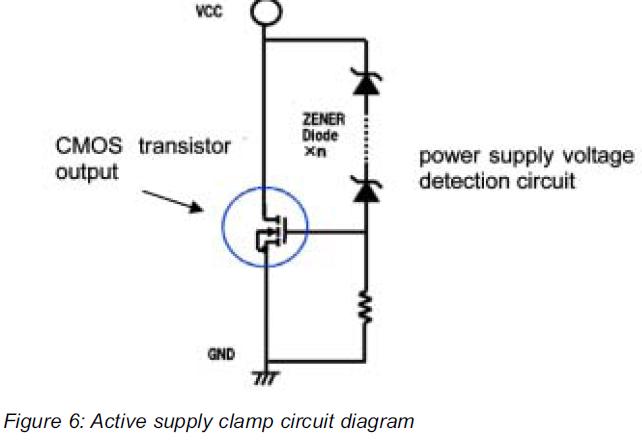
This article presents a high reliability 1200V High Voltage Integrated Circuit (1200V HVIC) for half bridge driver applications, aimed at reducing the IC's supply current by approximately 50%. The 1200V High Voltage Integrated Circuit (HVIC) is designed specifically for half-bridge...
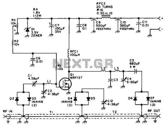
Using a power MOSFET, this amplifier can achieve a 2-W handheld radio power level, increasing it to approximately 10 W on the 2-meter band. A transmission-line RF switch is employed for transmit/receive (T/R) switching. The described amplifier utilizes a power...
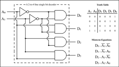
The Encoder and Decoder are different types of combinational circuits used to convert binary information to decimal, octal, and hexadecimal formats, and vice versa. A decoder is a combinational circuit that converts n-bit binary information into 2^n unique outputs....
Every dedicated DIY enthusiast creates their own electronic dice using LEDs as indicators. This eliminates the need to physically roll dice; simply pressing a button activates the electronic mechanism. The design incorporates safeguards to prevent manipulation for improved outcomes,...
Similar to the CMOS-based touch switch available on this site, this transistor-based touch switch can activate a load simply by the user touching a metal plate. It is designed to directly switch a relay, allowing it to be used...
If you require a small lamp that flashes for general use, there are numerous options available. Today, three lamp flasher circuits will be presented. The three lamp flasher circuits can be designed using different components and configurations, each offering unique...