
6 Battery Tesla Switch Power Mosfet Uses No Schottky Power Diodes
Warning: Undefined array key "extension" in /var/www/html/nextgr/view-circuit.php on line 468
Deprecated: strtolower(): Passing null to parameter #1 ($string) of type string is deprecated in /var/www/html/nextgr/view-circuit.php on line 468

In this circuit design, the objective is to achieve a low total circuit resistance, ideally below 0.1 Ohm, to maximize energy extraction from the system. The configuration employs two discrete voltage regulation stages to ensure stable operation. The first stage is depicted in the accompanying circuit diagram, while the second stage is integrated into the gate drive circuits of the MOSFETs, labeled as parts A and B.
The isolated power supplies must have their input voltage regulated to maintain a consistent voltage level, specifically around 12 to 13 volts. This can be accomplished through various means, including the use of mini switching regulators or other voltage regulation devices that can accommodate the specific requirements of the circuit. A critical design consideration is the separation of Battery 3 and Battery 6; they should not be interconnected as one battery is designated for charging while the other is for discharging. This separation is essential for the proper functioning of the circuit, ensuring that the charging and discharging processes do not interfere with each other.
The circuit is designed to utilize all six lead-acid batteries effectively, ensuring that the input voltage to the voltage regulator remains stable under varying load conditions. Achieving this stability can be challenging, particularly when the switch mode power supply requires a higher voltage input for optimal performance. Therefore, it is advisable to provide an auxiliary higher voltage source, such as 24 or 36 volts, to support the switch mode power supply in maintaining the necessary input voltage.
While efficiency may not be the primary focus of this design, it is imperative that the switch mode power supply delivers a reliable isolated 12-volt output to power the MOSFET switches. This configuration serves a dual purpose: it allows for the continuous monitoring of free energy production and mitigates the risk of battery overcharging, thereby enhancing the overall reliability and longevity of the battery system.If the total circuit resistance can be reduced significantly to less than 0. 1 Ohm & a load of 0. 4 Ohm or less is connected, over 1 Kilo Watt of free electrical energy can be obtained. There are two discrete voltage regulating stages, one is shown in the circuit below, while the other ones are shown in the mosfet gate drive circuits in part A & part B. The input voltage to the isolated power supplies must be voltage regulated in a similar manner as shown or you can use a mini switching regulator or any volt device. The positive terminals of Battery 3 & Battery 6 must not be connected together because one is part of the charge circuit & the other is part of the discharge circuit.
This circuit is intended to use discrete components to regulate the input voltage of the voltage regulator to 12 or 13 volts & to maintain that input voltage under all circumstances by making use of all 6 lead acid batteries. It is very difficult to maintain the correct input voltage to the switch mode power supply without some assistance from a higher voltage supply, such as 24 or 36 volts.
Efficiency is not important here, however what is important is that the switch mode power supply is able to provide an isolated 12 volt supply to all of the power mosfet switches. This will provide a permanent load on all of the batteries, which will not only show when free energy is being created but will help to prevent over charging as well.
🔗 External reference
Related Circuits
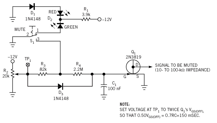
This simple circuit is a line-level audio signal muting switch based on a soft-action power on/off process. When the S1 switch is closed, R4, C1, and Q4 JFET are activated to mute the audio signal. The circuit operates by utilizing...

The circuit includes a current limiting feature that is more reliable than most commercial units. It employs three pass transistors that require heat sinks. Resistor R9 allows for fine-tuning of the output voltage to precisely 13.8 volts, while the...
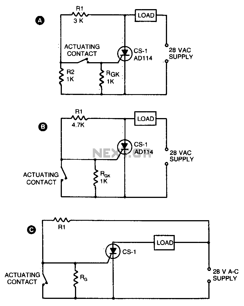
Two simple arrangements for resistive loads are shown in A and B. The circuit in A will provide load power when the actuating contact is closed, and no power when the contact is open. B provides the reverse of...

A high voltage power supply can be a beneficial source that can be utilized in various applications such as biasing gas-discharge tubes and radiation detectors. This power supply can also be employed for property protection through the electric charging...
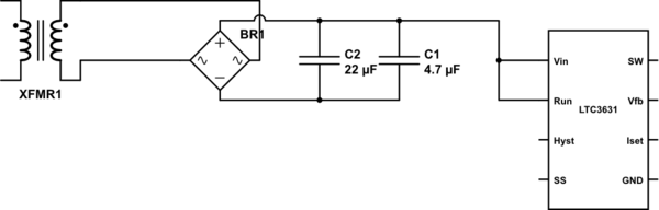
The leads from the transformer to the circuit are quite long (>5m). The 110V side of the transformer has been switched off frequently, which likely caused a spike on the secondary (24V) side. The input pin of the LTC3631...
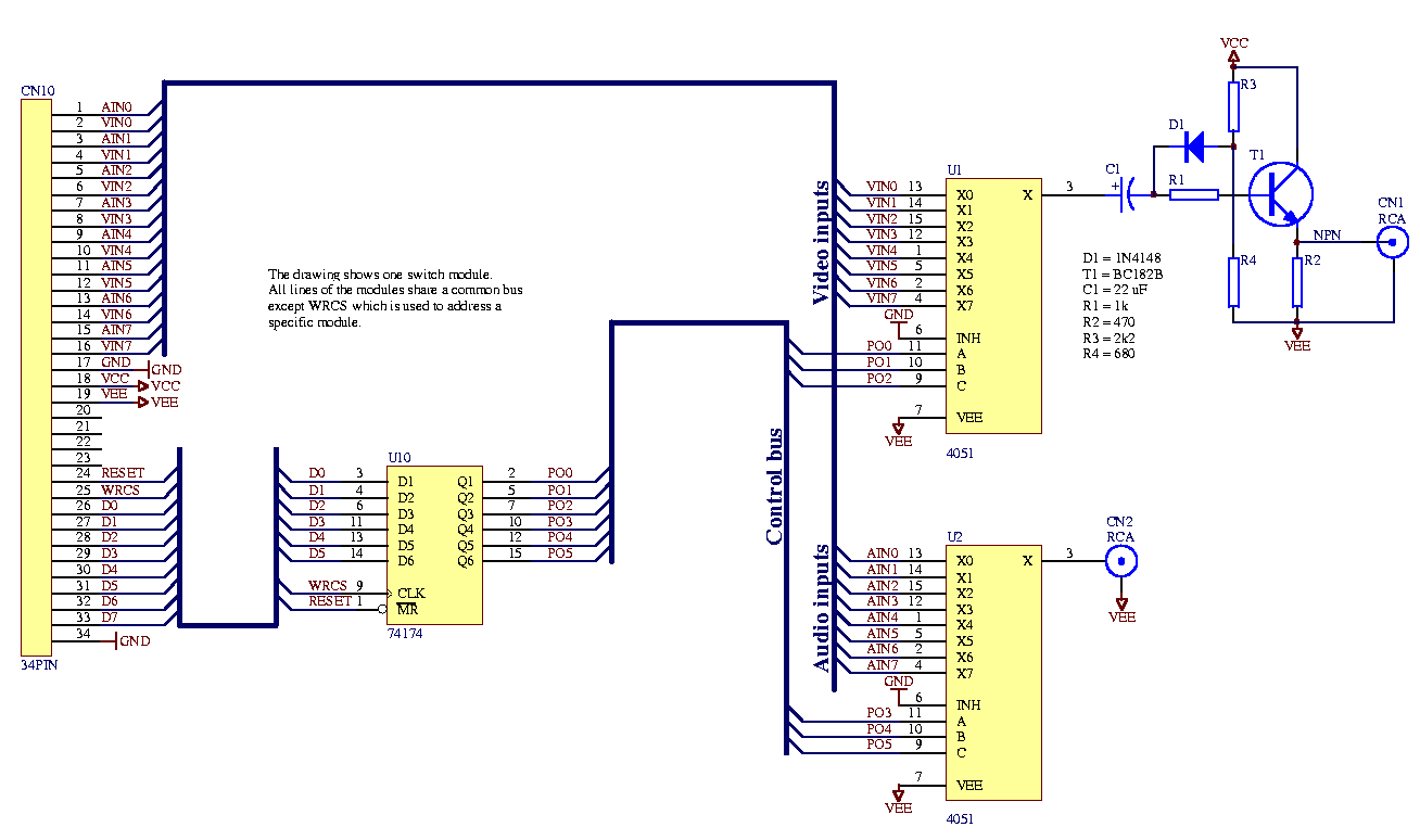
Each audio/video output can be switched to any of the eight inputs separately. One module drives one audio/video output and has a 34-pin connector to plug into the system interface. Video operational amplifiers (OPAs) can be used on the...